After fixing the 3DFX card, I sat back and looked at the LCD monitor I was using, and decided it just wasn’t right for the system. But the problem was, I’d ran out of suitable CRT monitors.
I did spot one in a skip at the local recycling centre a few days back, but as usual, you’re not allowed to actually recycle, and it was destined for the landfill somewhere instead.
So, since they are so hard to get shipped without being destroyed in the post, I decided to put a wanted ad up on Facebook marketplace. To my surprise, I actually received a message today from someone saying they had one, just a few minutes up the road from me.
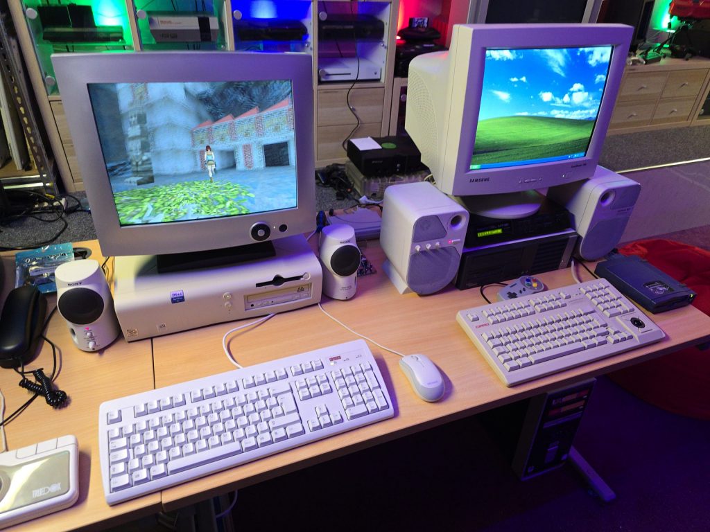
I went up to collect and met with a very nice guy with a 17″ e-machine CRT monitor in immaculate condition. I couldn’t believe my luck, it was exactly what I was after. And, he wouldn’t even accept any money for it, he was just happy it was going to a good home.
After getting it home, I gave it a quick clean and hooked it straight up to the VooDoo card.
It looks great sitting next to my Windows XP gaming PC.
The next step is to set up the network card so I can get some Grand Theft Auto multiplayer action going on.
I already have a few retro PCs in my collection, but I was missing one specific era, and that was the era when the 3dfx VooDoo cards hit the shelves. A friend of mine got one for his pc, and it was a complete game-changer back then. Everything went from blocky-looking textures to gorgeous, smoothed polygons.
The price of VooDoo cards is now quite high, costing around £120 for a working one. But where is the fun in buying a working one when you can buy spares and repairs for a 3rd of the price 🙂
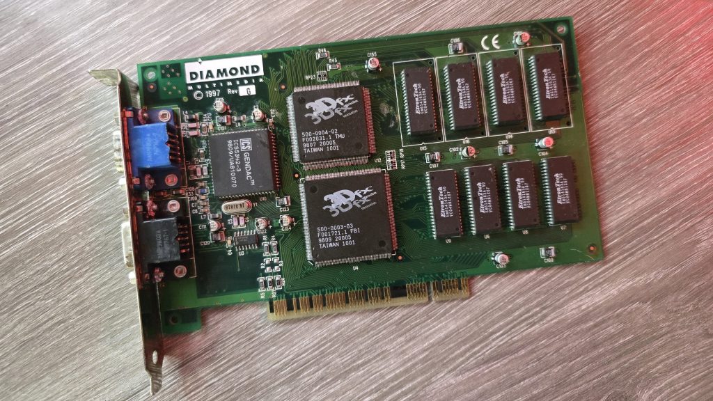
So for 39.99 inc postage, I picked up a Diamond Monster 3D VooDoo card. I had a small concern that the previous owner had admitted to fixing a couple of traces, which meant he had at least attempted to repair this card and had not succeeded. So could I do any better?
I gave the card a quick clean and inspected the traces that he had already repaired. I guess this card was chucked in a box at some point and had gotten scratched. They looked fine, but I re-did them just in case. I also noticed a couple of missing capacitors. There were only decoupling caps, but I replaced those anyway.
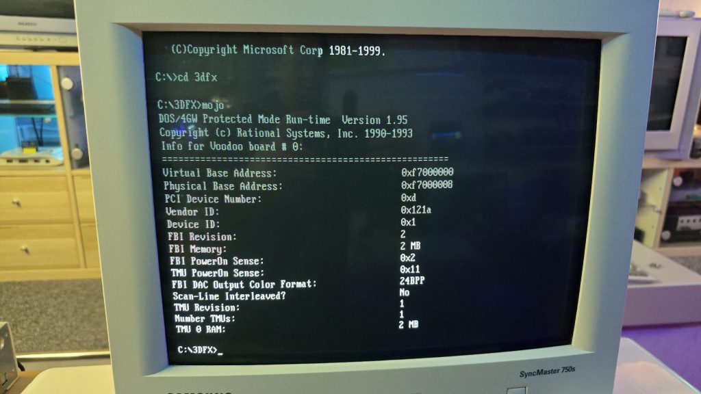
The next step was to test it out and see what state it was in. And things were not looking good. I ran the 3DFX diagnostic utility mojo.exe from DOS, and it just hung the system straight after DOS4GW.exe was loaded.
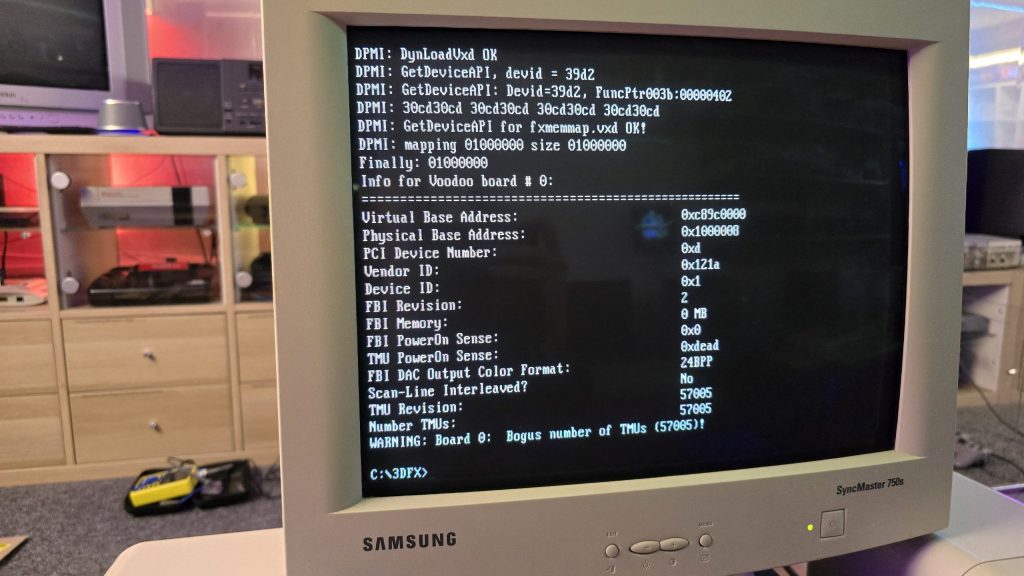
So I then tried booting into Windows 98. Amazingly, it did actually detect the card and installed the driver, but once installed, I got a yellow exclamation mark saying there was a resource conflict. Hmmm, that’s a bit odd. Just as a test, I went into the card settings and changed the memory address to a different one that wasn’t conflicting. I then launched the command prompt from Windows and tried mojo.exe again. This time, I got a different result.
Some noteworthy things here are that it was at least detecting the card now, but no memory on the card and the error code 0xdead didn’t fill me with confidence. The Bogus number of TMUs 57005 error is also hexadecimal for the word DEAD.
The above test gave me some clues, and I started to wonder exactly how a memory space gets assigned to a card when a PC turns on. Without changing the address in Windows, I was still just getting a complete hang in DOS, so it seemed this initial process wasn’t working properly.
I read a whole bunch of docs and figured out that when a PC turns on, the motherboard will probe the IDSEL pins on each PCI slot and communicate with the device on each slot to get the vendor ID and hardware ID. This part must be working, as Windows detected the device.
The next step involved BAR registers (Base Address Registers). This sounded promising. Essentially, each PCI device can have up to 6 BARs. When the card is initialised, these BARs will be queried, and the result of these queries will tell the PC how many chunks of memory space or I/O space the card needs to function. This part of the process is reliant on the PC talking to the card over the PCI address bus. If this process failed, then the card could report that it needs either an incorrect amount of memory or all of it!
At this point, I had already reflowed all the pins on the FBI chip and TMU, as I knew this was a common failure on these cards. But the problem remained, so I needed to check all the address lines. I tried to find a nice picture of the PCI slot pinouts, but since the card doesn’t have all the pins present, it was difficult to work out the pin numbers, so I went with a different approach. Every pin on the 3D X card should in theory, be connected to the FBI chip. So I put my meter on continuity, put one lead on the first PCI card pin and then ran the second along all pins of the FBI chip. As long as I got at least one beep somewhere, I assumed the pin was connected fine.
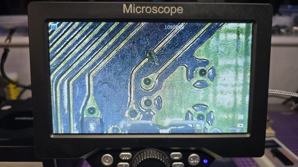
I eventually came across one pin that didn’t seem to be connected to any pin on the FBI chip. So I followed the trace from that pin and found a smoking gun!
Checking continuity between the PCI pin and the via after the break confirmed that there was no continuity. So I carefully scraped away at some of the solder resist and placed a bodge wire across the gap. After confirming connectivity, it was time to do another test.
Result!!! After booting directly into DOS and running mojo.exe again, no hanging and everything looked good to go.
So once again, I booted into Windows, this time with no device conflicts. I ran one of the 3DFX demos, and it launched fine, but with one small issue. I could see a pattern of dots on some of the textures.
This was a different fault now, so it was time to move my attention to the TMU chip instead. After carefully inspecting my re-flow work, I noticed the slightest solder bridge between two pins relating to the address bus between the TMU and the memory chips. After clearing this final issue, everything is now working perfectly and I am in possession of a fully working £39.99 VooDoo card.
Whilst sat browsing Facebook one day, I saw a post from someone local asking if anyone had a CRT for sale as theirs had broken, and they included a photo of their lovely 28-inch Sony Trinitron TV. I messaged him and asked what the fault was, and apparently the picture went off and was now just blinking the power LED with 2 blinks, which according to the service manual translates as Over Current Protection (OCP) triggered.
I said that if he was going to bin it, then I would like to pick it up and attempt to repair it. After all, you can’t really learn to repair stuff without having some broken ones to fix.
A couple of weeks later, he messaged me to say if I wanted to pick it up, then I could have it. So I got in the car and went and collected it. With some help from the Mrs, we got it home and down into my workshop, where I could then start my testing.
The first thing I needed was lots of information about CRT TVs and exactly how they work. And for this, I highly recommend watching videos by Randy Fromm on YouTube (Start with this one) After watching those, I had a very good understanding of what I was looking for. Even so, this Trinitron turned out to be quite a puzzle.
The first thing I did was test the TV to see what happened when I powered it on. And just as the guy had said, upon powering on, all I got was a blinking power LED flashing twice, then pausing and repeating. The issue with this error code is that it isn’t really very descriptive. Basically something, somewhere in the TV was apparently pulling too much current.
The other thing I noticed was that I wasn’t hearing any high voltage at all. Normally, when you power on a CRT, you will hear a crackling sound from the high-voltage circuit. So I downloaded the service manual for the set and started to look at all of the voltages to start with. This wasn’t that easy, because as soon as the TV detected the overcurrent, it shut down the power supply! Luckily, I have an oscilloscope, and this meant I could visualise the voltage for the very brief moment it was there.
From what I could see, the main voltages were present, specifically the 135V B+ voltage, which would go on to generate the high voltage via the flyback transformer. Another common fault on CRTs is the Horizontal Output Transistor; without this part working, you won’t get any image on the screen, and that part could easily pull too much current if it were to be faulty. But after testing it, it looked fine to me, and on my scope, I could see the required 135V pulses being sent to the flyback. So I really expected to hear some high-voltage crackling when the set powered on.
After looking around, I found that two fusible resistors had blown, which were right next to the flyback. I was hoping that they may have been the cause of the issue. But I wasn’t going to be that lucky, and after replacing the resistors, there was still no life in the set.
At this point, I decided I needed to test or replace the flyback. Unfortunately, I didn’t have any way of testing it at the time. So I looked around and luckily I found a replacement flyback on eBay from Malaysia. The part was new old stock, so I snapped it up and waited for it to arrive.
Fast forward to delivery day, and I swapped the flyback over, held my breath and hit the power button. For a split second, I heard a nice static crackle from the CRT, and then it shut down and sat blinking its LED at me. At least this proved that the flyback was indeed faulty.
The next few weeks were slow and painful. My bedtime reading was the schematics for all the various boards inside the TV. Every now and again, I would have an idea of something to test, so I’d run down, test it and come back to bed depressed that it still wasn’t working.
I went through all of the test points on the CRT and compared the waveforms to what was in the service manual and I just couldn’t find anything wrong.
I then had an idea, a potentially dangerous idea which I don’t think I would recommend to anyone! But I had basically run out of things to try.
The way the Over Current Protection circuit worked, is that it measures the voltage drop across a resistor and if that voltage drop was too high (two much current) it would trigger an OCP line that originates from the power supply board and gets sent to the microprocessor board which would then shut down the TV.
So what if I simply disconnected the OCP wire between the power supply and the processor? It wouldn’t get the OCP signal and would keep the TV running. Maybe then, whatever part was causing the issue would very quickly get hot, and using my thermal camera, I could see where the issue was.
Either that, or it would burst into flames and I wouldn’t need to worry about repairing it anymore 🙂
So, I pulled the OCP wire out of the connector block, pointed my thermal camera at the back of the TV and nervously hit the power button.
And……..
It came on and just worked. I carried on looking around with my camera, but nothing looked wrong. So I left it running for a while and carried on monitoring the situation. After about 20 minutes, everything was still fine, so I powered it off, reconnected the OCP wire and was straight back to a blinking light again.
After scratching my head until I had no hair left, my conclusion was that there wasn’t an overcurrent issue, but actually an issue with the overcurrent protection circuit itself.
I took a look at the schematics for this section of the board, didn’t understand how on earth it was supposed to work, so I went and watched some videos about over-protection circuits. The main thing seemed to be that for the OCP to trigger, there would need to be a large voltage drop across the current sensing resistor, but I was getting a 0.13V drop, which seemed perfectly fine to me. So the next step in the circuit was two transistors, which would monitor that voltage and turn on when overcurrent was detected. It looked like one of the transistors was outputting the OCP signal from its emitter, but with the voltage being in spec, there was no reason why it should. So, just for completeness, I swapped out both of these transistors as there wasn’t much else left that it could be.
After replacing these parts, I finally had a fully working CRT again and was able to reconnect the OCP wire.
So the moral of the story, although these newer CRT sets have the luxury of running their own diagnostics. Don’t just blindly trust what they are saying, and don’t rule out the fact that the diagnostic circuit itself could be the fault!
I would also like to point out that although this story seems quite short, these events were spread out over 6 weeks! But I do feel I have learnt a hell of a lot about CRTs on the journey so for that I am quite happy with myself.
Nothing left to do now but kick back and play a bit of Jumping Flash on the PlayStation to celebrate my victory 🙂
Back during my early school days, some of the classrooms had BBC Micros in them along with a beige metal CRT monitor with Cub written on it. These displays were nicely matched to the BBC and were very common at the time.
I happened to log into Facebook at a perfect time last week when a guy I know (Zeb) posted on the Acorn group that he had a Cub monitor free for collection for whomever claimed it first. He doesn’t live that far away from me so I jumped at the offer.
Zeb then messaged me to say, he forgot to mention that it was broken and did I still want it. To most people this would have put them off, but for me it made the offer even better! Now I had a reason to learn more about CRT repair!
I went and collected the monitor and brought it back home and after an initial inspection I plugged it in to see what happened. The monitor fired up, I could hear the high voltage working and then a single horizontal line appeared across the center of the screen so I turned it off before any damage was done to the phosphor.
The schematics for these monitors are available to download so I grabbed them and started to look at the vertical deflection part of the circuit. This seemed to get it’s power from a section of the circuit that contained a nice big capacitor that was connected to ground. This looked like a perfect candidate for the fault so I removed the capacitor and tested it with my ESR meter and sure enough it was shorted. I didn’t have a replacement so I ordered one and decided to do some more research while I waited for it to arrive.
I soon discovered that this fault was actually a fairly common issue with these displays and it often kills one of the fusible resistors at the same time. So I tested this and sure enough that resistor was also dead so I ordered some replacements.
Once those parts arrived I fitted them and turned of the monitor and was greated with full vertical deflection.
I was pretty happy at this stage but that was short lived.
I connected up the BBC and powered the monitor back on. Instead of a nice picture, I got a weird squiggly pattern and then magic smoke started to come from the monitor so I quickly powered it off again. The smoke had come from the resistor I had replaced. So it looked like there was a bigger issue that had possibly caused the capacitor and resistor to die in the first place.
I then spent a couple of hours looking at the schematics and testing capacitors and resistors in the vertical deflection section and everything i looked at tested fine.
The service manual had several images of test points and what the waveforms should look like. So I grabbed my scope and started looking at these signals. Most of them were fine but I had no field output signal. I was pretty convinced now that the TDA1170 IC was internally shorted and was causing a high current draw which killed the resistor.
So, I went back on eBay and found out that these ICs were still available. A couple of days later it arrived and as soon as I finished my day job and went down to my workshop and fitted the new part. Whilst holding my breath, I powered the monitor back on and everything seemed to be fine, full vertical deflection and no smoke.
It was now time to connect the BBC back up and see what happened. This time I got a nice clear image and still no smoke!
This was a pretty satisfying repair and during this I have been watching a bunch of videos about CRT theory and repair. The best ones I have found so far are the CRT workshop videos by “Randy Fromm” on YouTube. I would highly recommend watching these as they contain a wealth of information and real world experience within them.
I also have another CRT here now which I am trying to repair, which is a 28inch Sony Trinitorn that has an over current protection fault. That was is going to be a bit harder to troubleshoot but my understanding of how these CRTs work is much greater now so I am confident that one day I will get it fixed.
One of the computers I have setup on my new desk is the Yamaha CX5M MSX Computer. The only issue with that is the UK version of this machine only outputs a composite video signal and that is going to look terrible on an LCD monitor.
After looking around the internet for bit, I came across the TMS RGB V2 mod from videogameperfection.com. This device works on many different systems that use the TMS9928A and TMS9929A chips, such as the MSX.
The fitment of the device is pretty simple, you just place it over the pins of the TMS chip on the underside of the PCB, and then solder the holes that have the metal ring around them.
Once that was done I routed the wires to the back of the case where I made a small cutout and fitted a mini DIN connector to output the new RGB video signal.
I then made up a quick mini DIN to scart cable and re-assembled everything. After connecting it to my Open Source Scan Convertor (OSSC), I was greated by a beautiful sharp RGB image being output to my LCD Screen.
I think I am going to be much happier now, exploring the MSX software library with a nice sharp picture. All in all, a good afternoons work 🙂
A while ago I purchased some UV overlays for the Vectrex. These overlays require a UV light source to make them glow. At the time when I purchased them, my 3D printer couldn’t handle the size of the Vectrex screen so I made a frame using multiple 3D printed parts and glued them together.
I was never really happy with the design though so decided now I have larger printers, I would re-visit this project.
I also decided to experiment which switching filament during the print so I could use transparent filament as a diffuser.
This still may not be my final version, but I am pretty happy with how this has turned out for nowadays
I now have my computer desks in and setup so just thought i’d do a quick post showing what it looks like. Still got some cable management to do and then I need to make a start on cabling up to 20+ consoles on the other side of the room!
I was hoping to get everything finished off this week as I have another week off work. But think this is going to turn into a longer project than originally expected. It took me two hours yesterday just to sort my cables into two piles of power and video cables lol.
The Virtual Boy has always intrigued me, a bit like a VR headset, it’s one of those devices that people cannot show you what it is like in a video or a screenshot. You just have to experience it for yourself.
I had previously heard a lot of people complaining of headaches and eye strain etc, but a lot of people suffer from those sorts of things with modern VR headsets too and I’ve never had any issues with them. So I finally decided to take the plunge and add one of these devices to my collection along with a flash cart so I can experience the entire library.
I must say I am actually quite impressed, I mean it’s not actually VR in any way, it’s more along the lines of a 3D Gameboy, but the effect is really good and the games I have played so far have also been very enjoyable.
The device is also completely different from anything else released back then, so it looks great on display and always draws attention to itself. No regrets at all about finally adding this to my collection, especially the fact it was my birthday present.
I’ve had the Vectrex for a while now but didn’t own any original games for it. I started by using a multicart and then moved on to the Pi-Trex.
The issue with this is the original games used to ship with colour films that fitted over the screen to add some colour to the vector art. That issue is now a thing of the past as I have not only purchased my first original game, but also purchased a pack of 9 original overlays from one of the retro Facebook groups.
So here for your viewing pleasure is Scramble running on the Vectrex with its matching overlay!
I have had a 21inch CRT in the bedroom for a while now with the Playstaion 1 and 2 hooked up to it for lightgun games. It did the job and was free so certainly no complaints. But I have always been on the lookout for a 21inch Sony Trinitron flat screen to take that spot.
Well, I am still on the lookout. But! I did comes across a Samsung 21inch CRT flatscreen on Facebook Marketplace for free. I messaged the guy as soon as I saw it but didn’t hear anything back so just assumed I missed it. Then 3 weeks later I recieved a message to say it was still available if I wanted to collect it. By the time I finished reading his message I was already in the car!