This is the second computer from the recent batch of computers I’ve obtained to test and fix if required.
It’s an Acorn BBC Model B with 32k of RAM, and like the Atari 800XL, this one was also in non-working condition. I did a very quick power up test and was just met with a continuous beep. With the BBC, this basically means that no code is being executed, so rather than the beep being silenced very early on in the boot process, it just sits there with an irritating tone blasting out of the speaker.
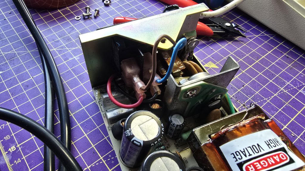
Since I knew this machine had been sitting in storage for a long time, the first job was to swap the RIFA capacitors out before they let out the magic smoke. I had these capacitors in stock, so I removed the power supply and replaced both of the RIFAs and also one of the electrolytics that is a common failure point.
With that job done, I re-assembled the computer and started the standard troubleshooting process.
The first test was checking the voltages, both the +5v and -5v rails were within tolerance , so no issues there. The next step was to check the clock signal.
The BBC has a 16Mhz crystal oscillator which feeds into the BBCs video ULA. The ULA then takes this clock and divides it into multiple clocks for different parts of the system. The outputs run at 1Mhz, 2Mhz, 4Mhz and 8Mhz. Or at least they should! Checking these pins on the Video ULA showed that only the 1Mhz clock was running and the others were all dead.
Unfortunately, this is far from ideal as this is a custom chip and not a cheap one to replace. But since I had a fully working BBC Model B on the shelf, I was able to borrow the video ULA from that to see if the problem would be resolved.
It was never going to be that easy though was it! The BBC still emitted the same failure tone. But there was one change, and that was we now had clock signals and could see activity on the address and data bus, so at least we were trying to execute code now.
Since signals were looking ok now on the CPU, I figured memory chips may be the next issue. There is a little trick you can do on the BBC where you change jumper 25 (I think?) from position 1-2 to 2-3 and this makes the BBC think it is a 16K machine. If the machine boots in this config, then you know there is faulty memory in the upper half of the RAM.
This configuration didn’t work for me either, so if there is a memory fault, it’s within the lower 16k or in the lower and upper 16k if there are multiple failures.
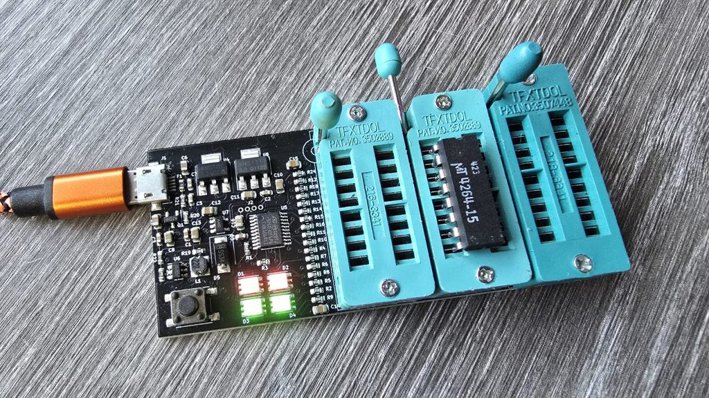
The next step was to grab my thermal camera and see if anything was obvious. With this, I spotted two of the RAM chips were stone cold whilst the others were nice and warm. Starting with these two, I removed them from the board and tested them in my RAM tester. This confirmed that both of these chips were dead. So, I put two sockets in and placed two new chips in the sockets.
Another power on test revealed we still have the same problem. It was time to face the hard truth, any one of these chips or combination of them could be faulty. So I set about removing them all from the board, testing them and fitting sockets in their place.
Tedious work, but eventually I had a board fully fitted with RAM sockets and a full test of verified RAM chips. A total of 5 RAM chips tested faulty.
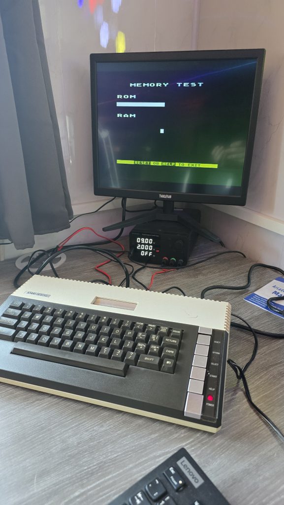
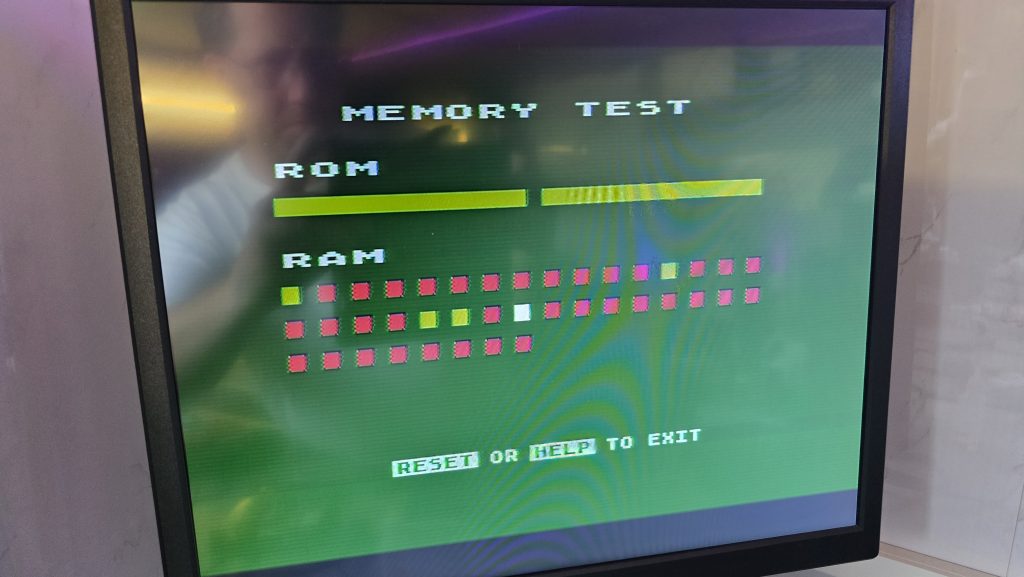
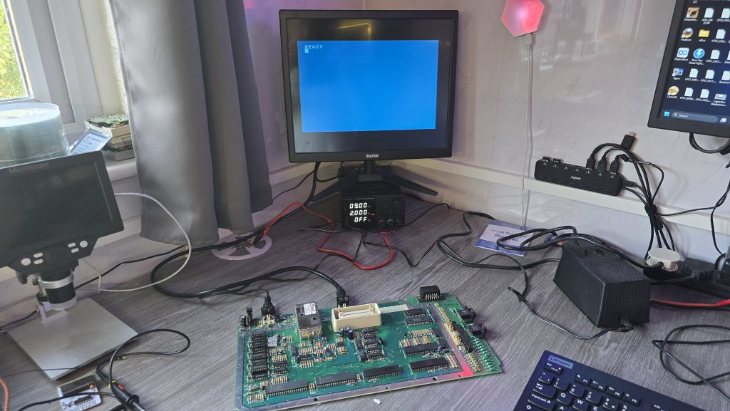
With my fingers crossed, I power it up for another test. This time I got the normal startup beep! Could it be that we finally have a working computer? It was time to move the BBC over to my Cub monitor and see what we get.
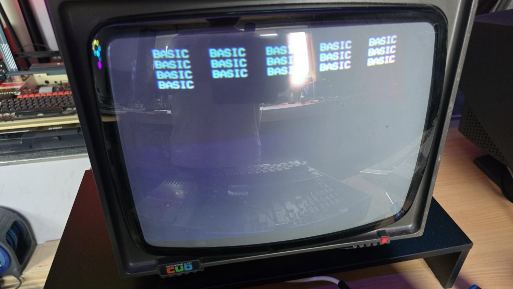
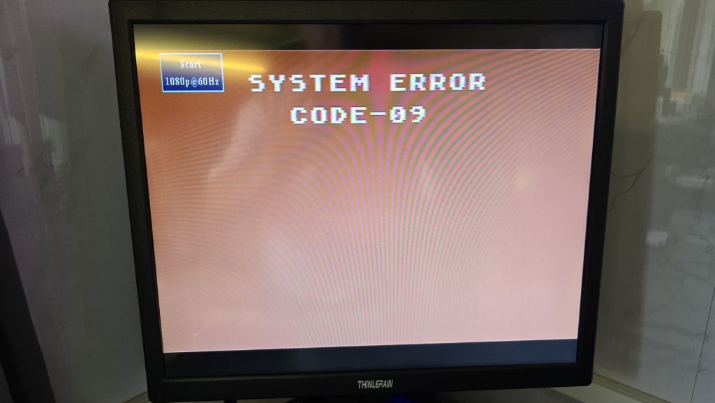
Erm, well lets call that progress at least. But this is not what I would expect from a working computer.
Every now and then I like to test out AI’s skills on repairing vintage electronics. So I gave it a detailed explaination of what I was seeing and it assured me 100% that I had faulty RAM chips. I told it that it was 100% wrong and that my experience showed that when you get weird repeating pattern things like this, it’s normally an addressing issue. It told me that I was 100% wrong, so I completely ignored it and started troubleshooting my addressing issue 🙂
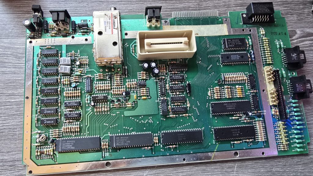
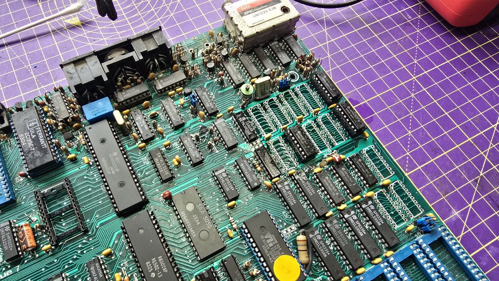
I went back to the schematics and looked up which ICs sat between the RAM chips and the CPU.
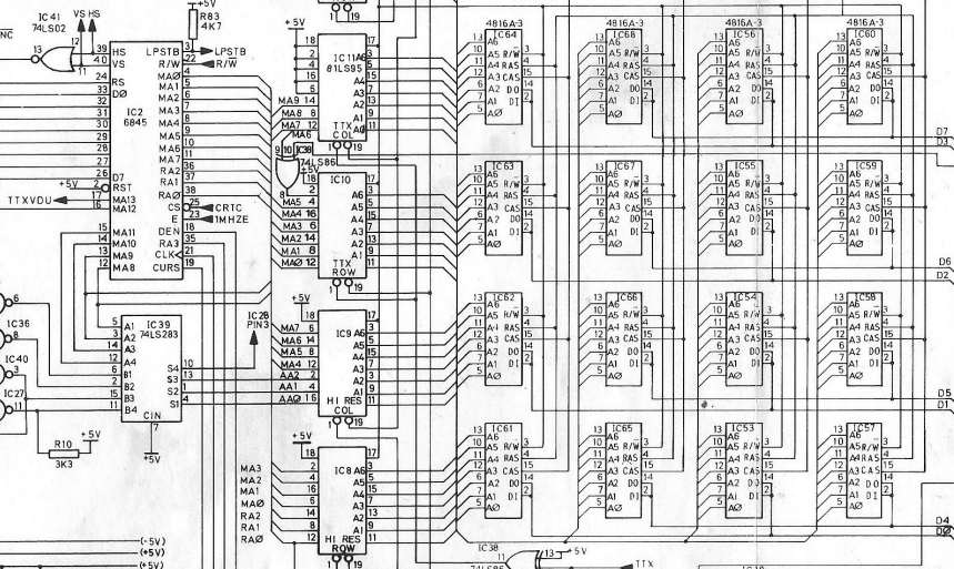
As you can see, the address lines from the RAM chips all connect via IC 8,9,10 and 11 to the 6845 CRT Controller chip.
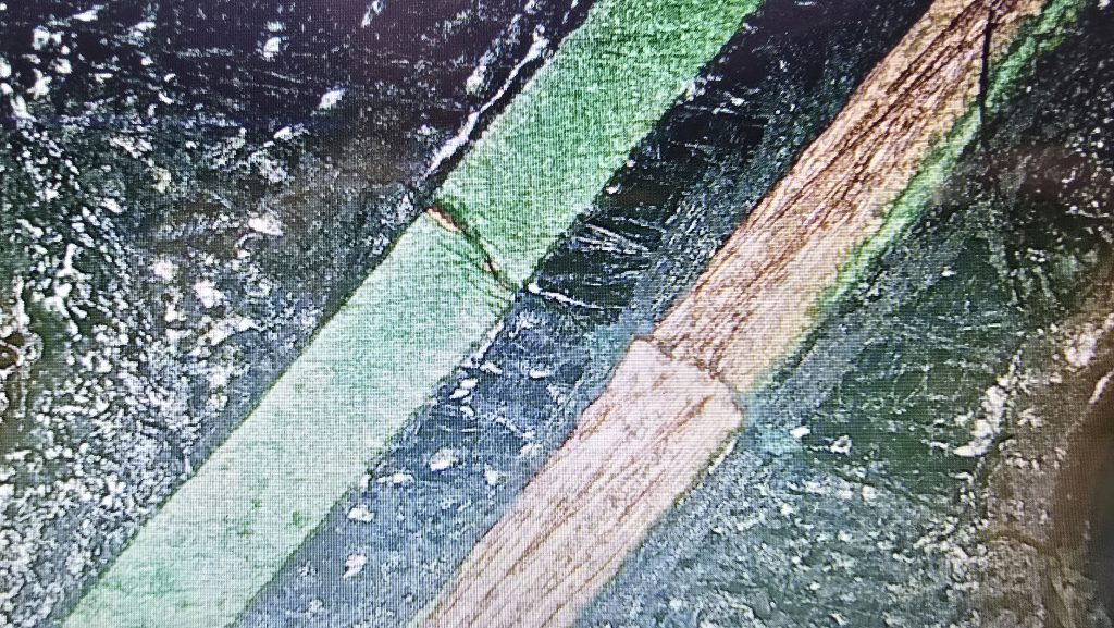
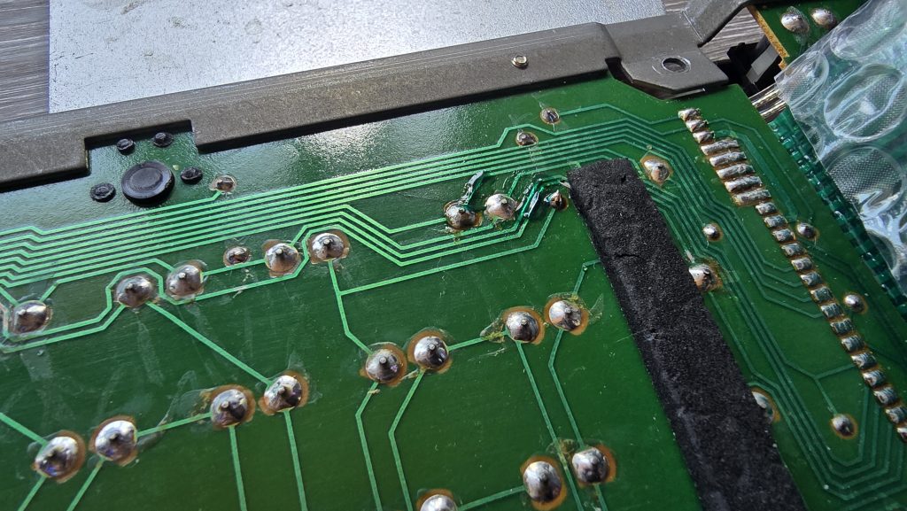
I went through all of the A0-A6 lines on each of the chips which all appeared to have good looking activity. But when I tested the MA lines on the left side of the chip, I noticed a few of them were just floating.
I made a note of which ones were missing across all of the chips and found that lines MA3,MA4,MA5 and MA6 were all suspect. I checked these signals on the 6845 chip and saw the same issue there. Since these were outputs from the 6845, I suspected another faulty IC, so I grabbed the one from my working computer and put it in place.
Another power on test, and…….
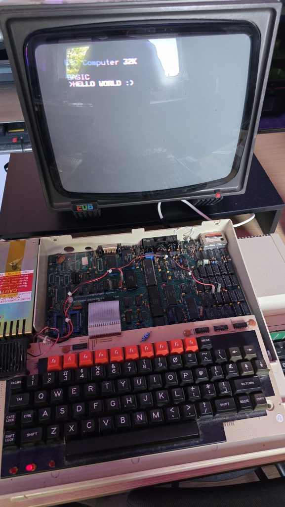
We finally have a working BBC Model B!
I still need to do some final checks on this one and make sure it can load software from the cassette port (It’s never had a disk drive fitted so doesn’t have the DFS Rom fitted).
Once I’ve done these remaining tests I’ll be putting it back together, giving it a good clean and then this one will also be going up for sale. It is missing the clear plastic strip that goes across the top of the keyboard, but apart from that it’s in pretty clean condition. These strips can be picked up off ebay occasionally, but I’ve already spent too much on this repair, mainly due to the Video ULA which cost £45 on it’s own. There was then the 6845 at £12.25 and 5 memory chips at £12.50 making the total cost of repair on this one £69.75.
Was it worth it? Including my time if I was to charge labour, then probably not. But this isn’t about making me any money and I’m not charging any labour on these repairs. A BBC Model B lives to see another day, and any profit from the sale will be going straight to my friends wife and his family.
So, if you are interested in getting your hands on a BBC, then keep an eye on my shop. I’ll also be listing on eBay for people more comfortable purchasing that way, but the cost will be slightly higher on eBay.
The next computers to look at are some C64’s. Will they work? Stay tuned to find out 🙂