Part 1 – 17/02/2026 –Design and making of the first panels
A while ago, I was given some arcade machine parts. This consisted of two original arcade boards and an arcade machine control panel. The boards were in need of repair, and the control panel needed a good cleanup. But the end goal was to build a cabinet that would eventually use these components if at all possible!
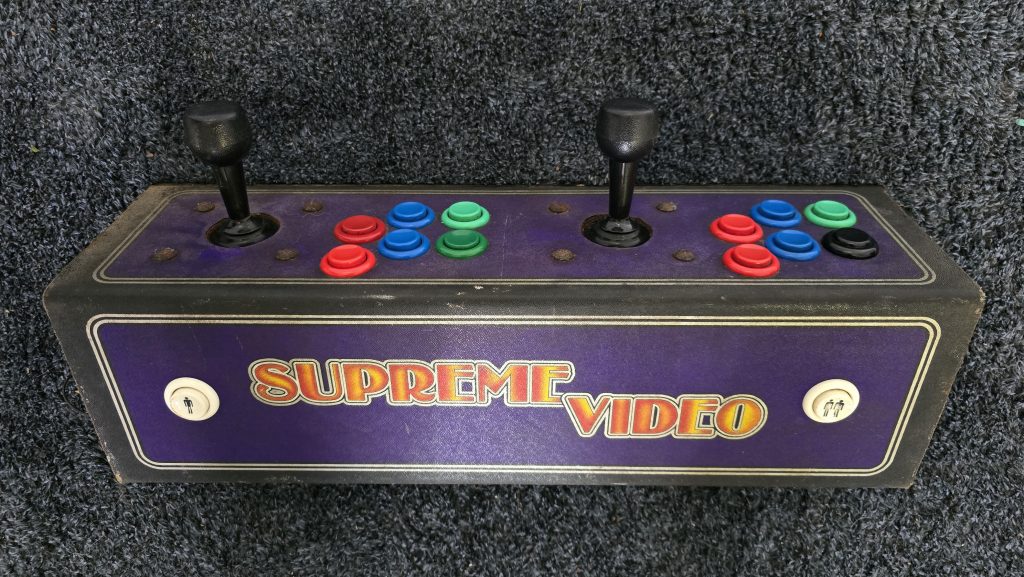
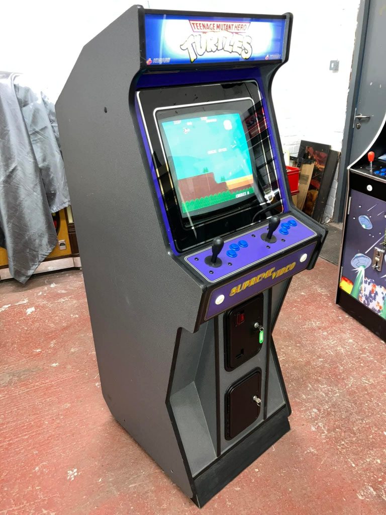
Doing a bit of a look around on the internet, I found an example of a cabinet that was using this control panel. It looked a bit different to the standard cabinet design with some nice angles on it, so I have decided to use this as my template and try to replicate this cabinet.
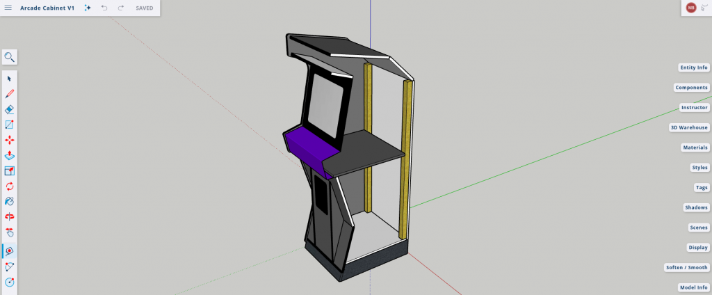
The first step was to work out some measurements and knock up a 3D model to make sure everything was going to fit together correctly. I always use SketchUp for this simply because it’s what I got used to and find it quite intuitive to use.
After this, I took one of the side views and exported it as a PDF. Using Adobe Reader, I then printed it out to scale across several sheets of A3 paper and taped them together to give me a template to transfer onto 18mm plywood.
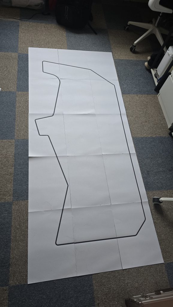
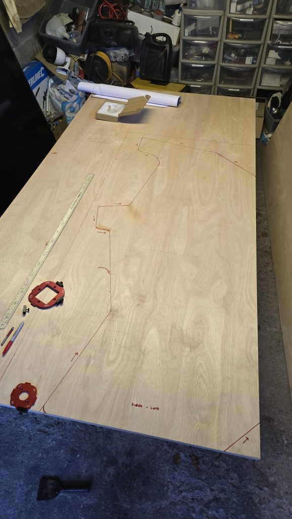
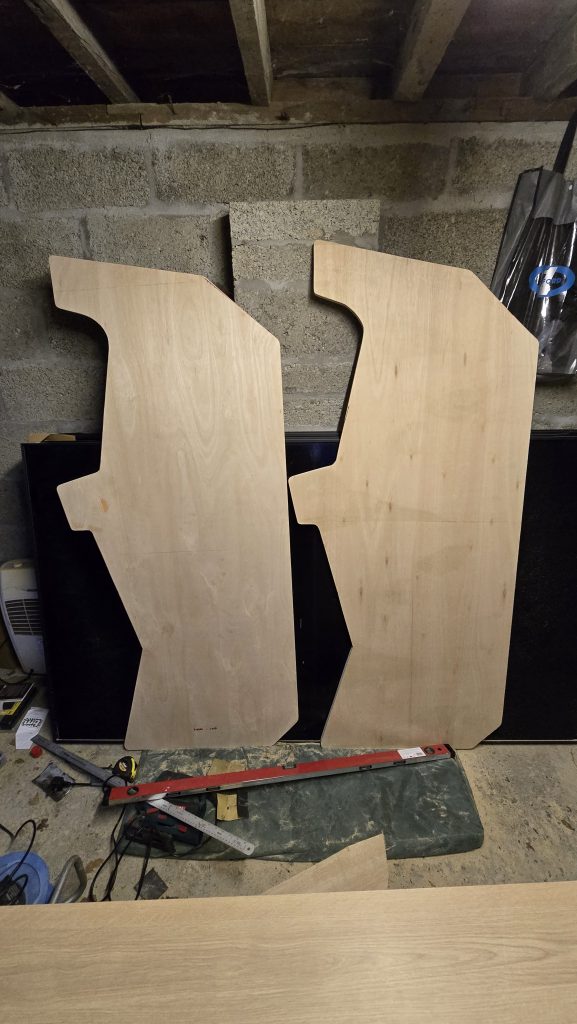
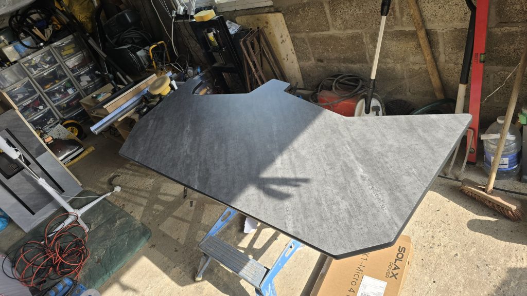
Now that the template was transferred, I cut out the first side, smoothed all the corners and then clamped it onto the second sheet of plywood to get an exact copy. After cutting the second side out, I clamped them back together and once again sanded the round corners to make sure everything matched perfectly.
So that concludes the first part of this build. The next step will be to make some of the internal panels and turn this flat cabinet into a 3D object. If you want to keep up to date with this project, then subscribe to updates, and i’ll put out a notification whenever this project is updated!
Part 2 – 22/02/2026 –Making the cabinet freestanding
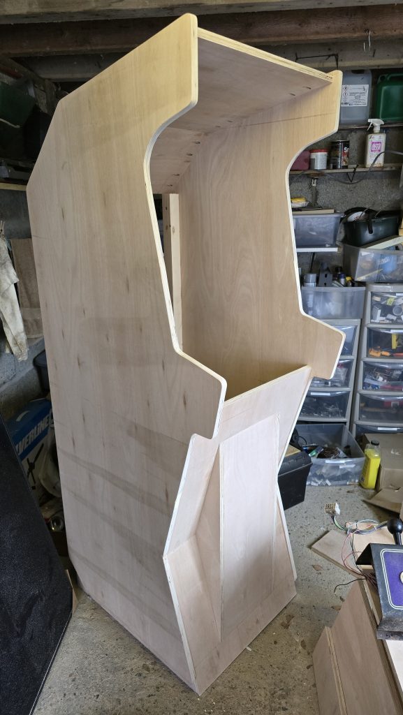
I’ve had a spare couple of hours over the weekend, so I concentrated on cutting some of the joining panels and also the small riser that is at the bottom of the cabinet. T
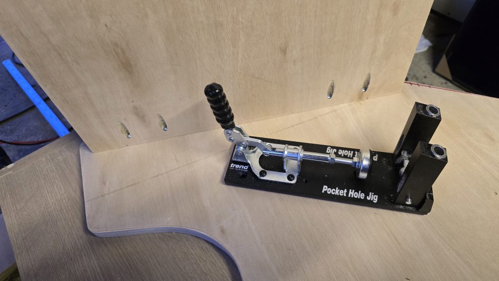
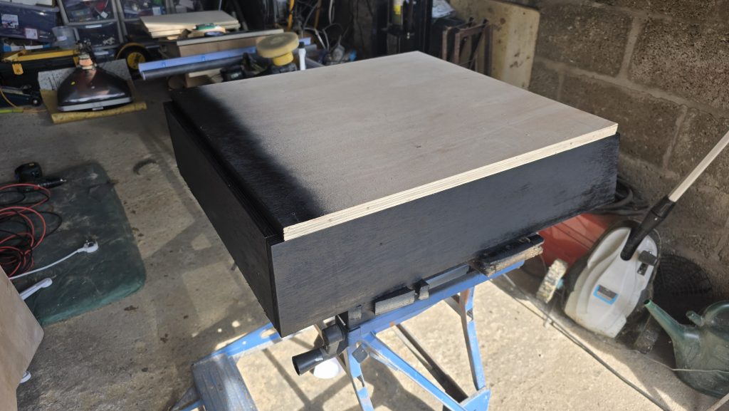
I’ve joined all the panels together using a pocket hole jig and screws. This way, it will keep the outside panels nice and tidy without visible screw heads everywhere.
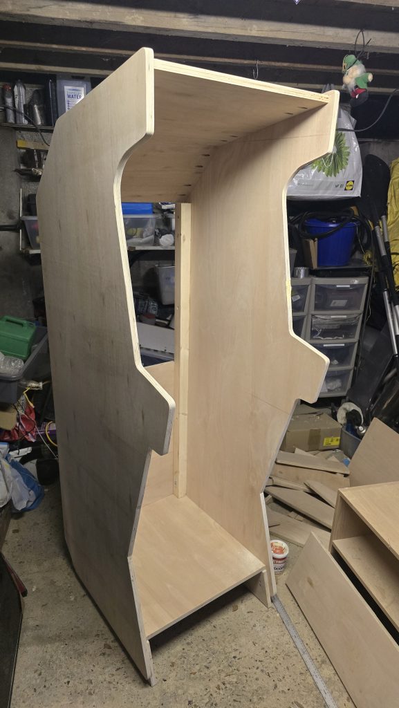
The cabinet is now a freestanding unit and is really starting to come together.
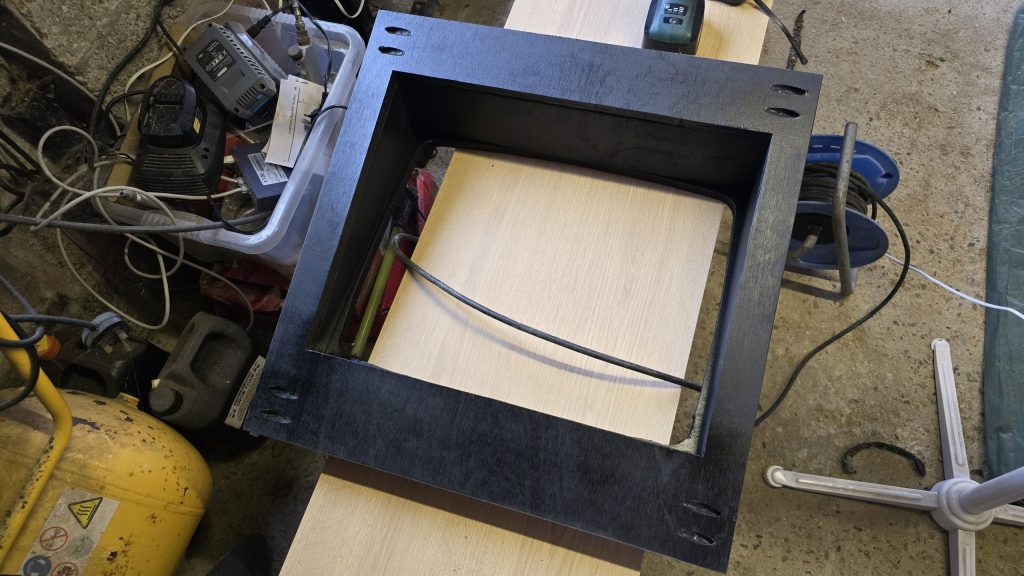
The next stage will be to build the part where the coin mechanism will go. I know it’s easier to have a button to add credits, but I want this to mimic the real experience as close as possible.
But, instead of using coins, I’ve managed to grab some official SEGA tokens off one of the Facebook arcade groups. So these will be my currency of choice.
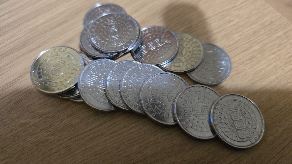
Stay tuned for more updates!
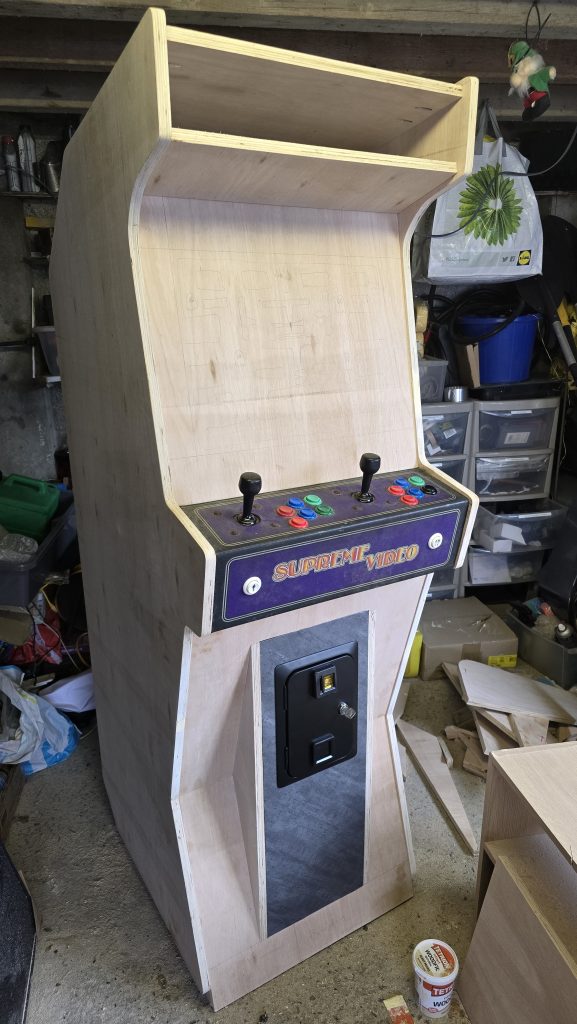
Part 3 – 01/03/2026 –Adding the control panel, coin slot and preparing for the display mounting
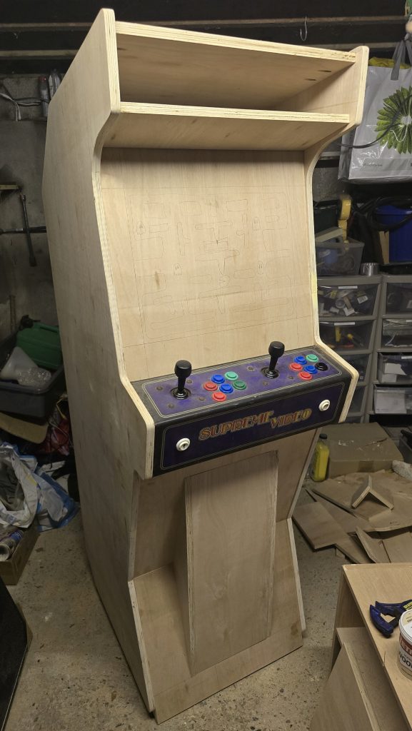
A few more hours in the evenings spent working on the cabinet, and also a bit of time at the weekend. The first step was to start building the front of the cabinet. There were quite a few angles to cut for this one, but having all the measurements on the 3D model really helped out here. After marking out everything and then cutting it, assembly was quite straightforward.
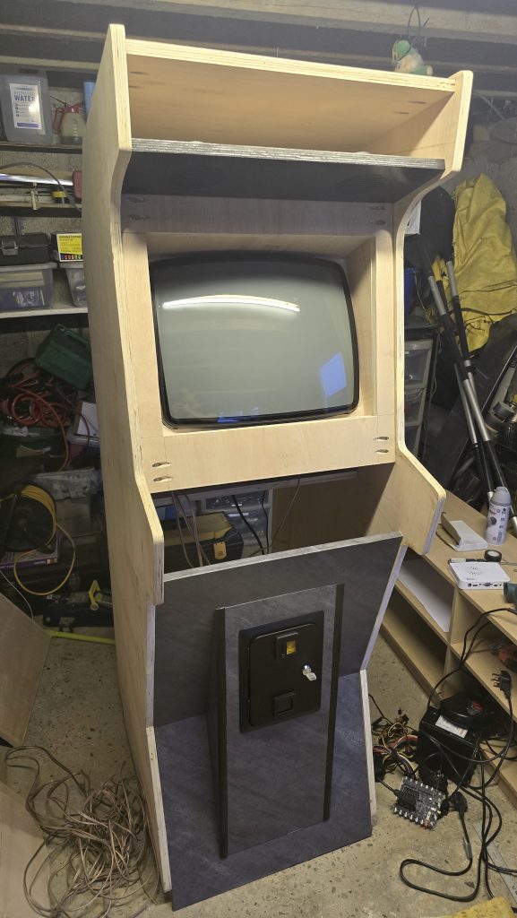
At this point, I decided mount the control panel next so I could make sure that everything was at the right height and aligned properly.
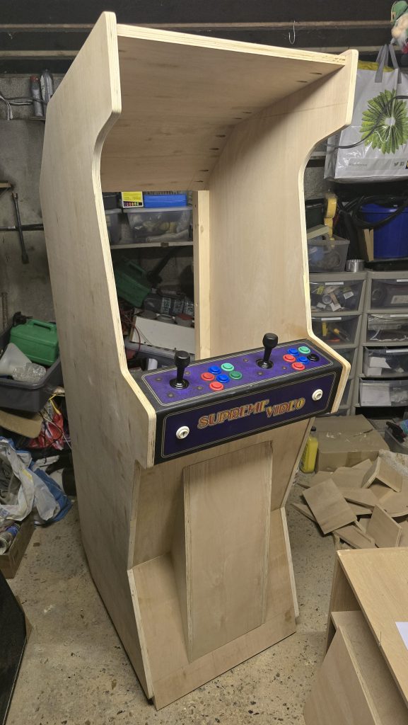
Everything is looking good so far, so I continued and added the support where the marquee will go, and also the front panel for the display mounting. I will need to remove this again once I’ve measured the actual CRT display. This panel will have clear Perspex fitted to it and the bezel graphics at some point in the future. The CRT display itself will be set a couple of inches back from this panel.
The next step for this session was to fit the coin door, and since the vinyl wrap had also arrived, I decided to wrap that panel just to get an idea of what it was going to look like..
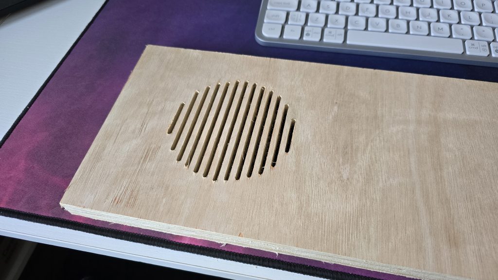
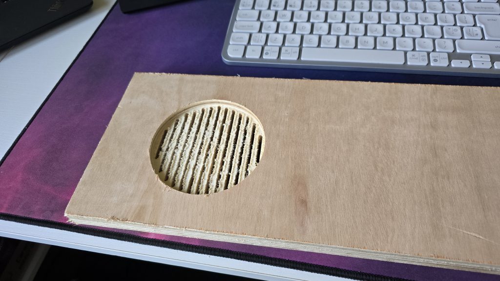
Finally, I got around to setting up my mini CNC machine to start experimenting with the speaker grills. I knocked up a quick design and set it to cut on a scrap of wood. I think it turned out pretty well and is probably what I will use on the final design.
So that’s it for this session. Next, I will be looking to start routing out the slots for the t-slot moulding, and possibly wrap the side panels. Then it will be concentrating on mounting the CRT tube.
Part 4- 12/03/2026 –Fitting the CRT, Wrapping the bottom part of the cabinet and testing the electronics
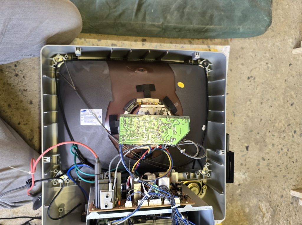
A slight change in the order, but I decided to get the CRT part sorted. I had been putting this off, as I hadn’t quite decided how it was going to work, but I decided to just take the plunge and just get on with it.
The first step was to take apart the TV I was using and get the actual CRT removed from the old casing.
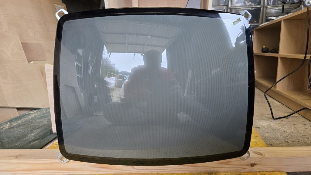
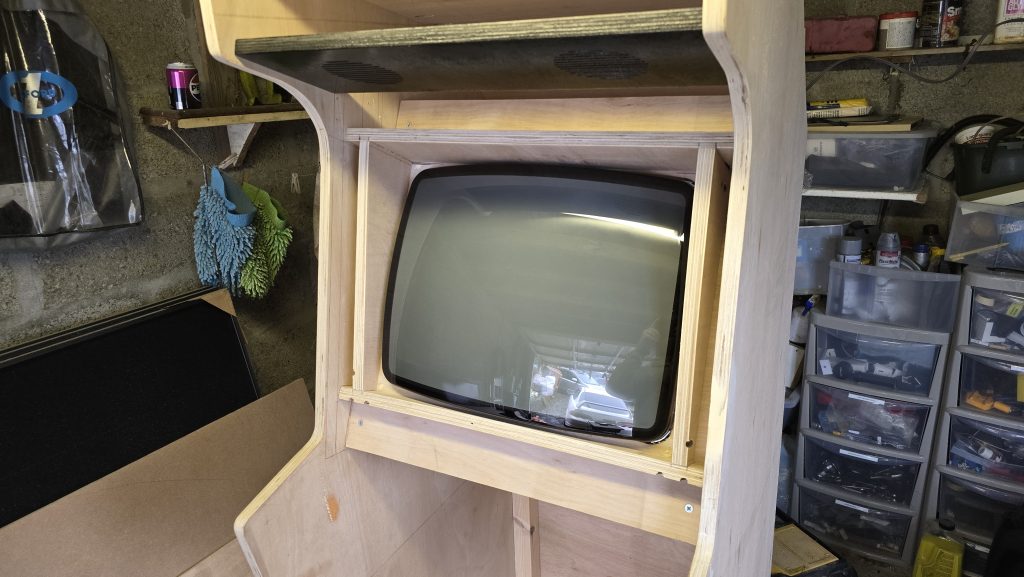
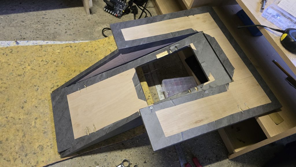
The next step was to make a template for the tube on paper and then cut it out of plywood so the CRT was firmly mounted with a plywood surround.
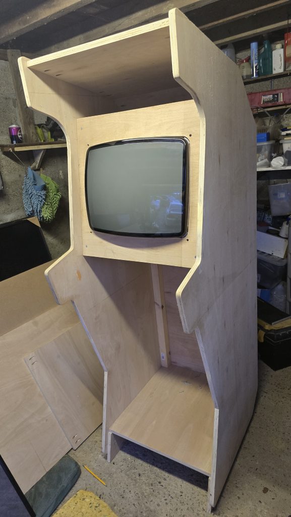
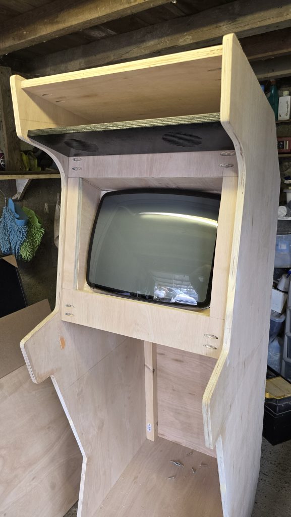
Upon standing in front of the cabinet, it was obvious that the angle of the screen wasn’t right, and it needed to be tilted further backwards. I had expected this would be the case and wasn’t sure how to mount it the way I wanted. After titling it and just staring at it for a while, A plan formed in my head, and I started to construct the border for the screen. The insides of this will eventually be painted matt black to stop any reflections, then the acrylic bezel will sit over the top of it.
After that bit was sorted, I decided to finish wrapping the bottom section of the cabinet since I already had it removed/
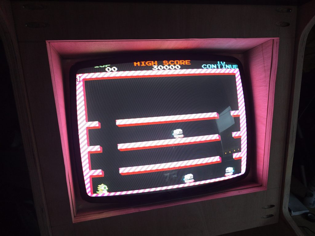
Now that it was all back together, I thought it was about time I gave the electronics a test. So I wired up the CRT, connected up the Jamma “SuperGun” board and connected up the Pandora box. For now, I just plugged in one of my Neo Geo Joysticks as I haven’t done the wiring for the control panel yet. I also took this opportunity to connect up the coin mechanism, as I hadn’t been able to test this out yet.
I am now waiting for my acrylic sheet to arrive. Once this is here, then the bezel and marquee will be the next things I tackle. Check back soon!
Part 5- 26/03/2026 –Wrapping, painting and starting final assembly
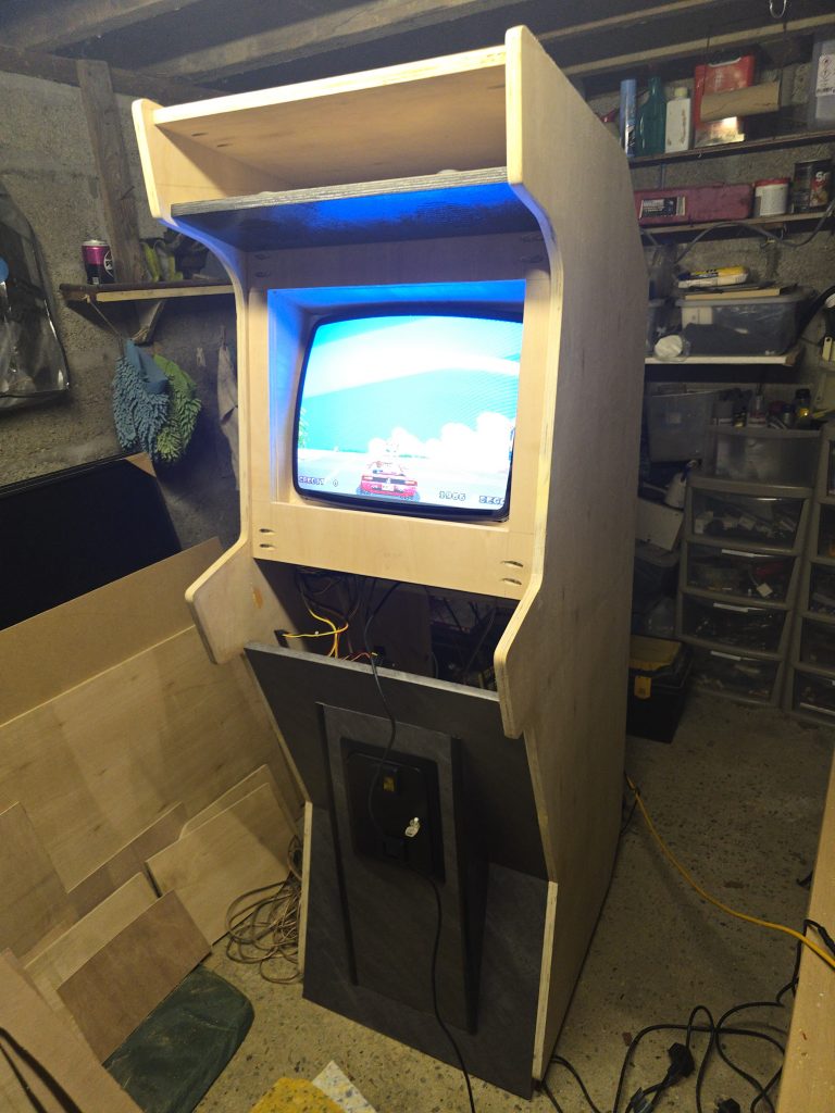
The acrylic has now arrived, but I’ve decided to leave that bit until last now. So in this update, I have now wrapped both of the side panels and painted the inside edges of them black. I’ve also painted the small riser for the bottom of the cabinet and the screen surround.
With all of these parts completed, I decided it was time to start the final assembly of the cabinet into its final location. So I dismantled everything, and bit by bit, I took the parts into the house and started reassembling them.
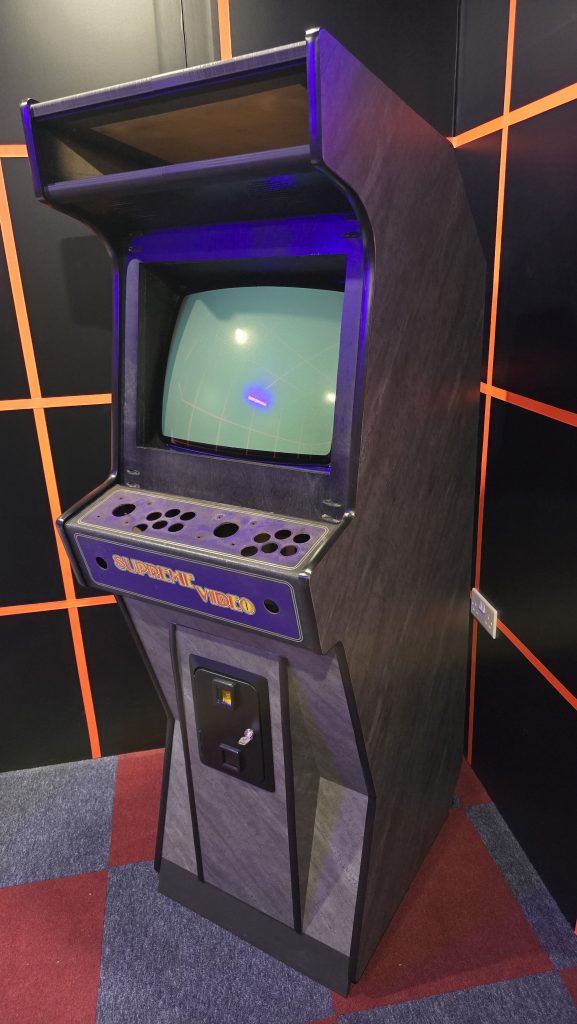
The result is starting to look pretty close to the original cabinet design.
The next step will be cleaning the control panel up, installing the new buttons and micro switches, then wiring up all of the electronics again. Hopefully, I am now coming to the final stages of this project. Check back soon for possibly the last update on this project!
Part 6- 1/06/2026 –Final Assembly and Testing
It’s been a while since my last update, as life got in the way. But the cabinet build is now completed. The next stage in the build was wiring up the control panel. For this, I used a new Jamma harness, which I purchased. I removed the actual Jamma connector, but wired up everything using the correct colour scheme to make any future troubleshooting a bit easier.

Once I had the control panel all wired up, I couldn’t help but test out a few games. It was at this point that I ran into some issues.
The Pandora Box that I was planning to use, although fully functional, just didn’t run things smoothly. I was getting stuttering where games should have been scrolling smoothly. Also, games such as OutRun really struggled speed-wise at the beginning of the game. I knew that this was going to annoy me, and anything less than perfection was never going to be acceptable.
At this point, I made a slight change in direction. Instead of using the Supergun with a Pandora box, I decided to go down the good old Raspberry Pi route.
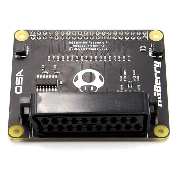
I now had a couple of things to sort out. After a bit of reading around, for controls I went for the Ultimarc I-Pac 2 (which I have used in the past to great success), and for video I went with the RGBerry Scart interface, which would allow me to connect the Raspberry Pi 5 up via an RGB Scart Cable. (https://thepihut.com/products/rgberry-scart-rgb-arcade-hat-for-raspberry-pi)
With all of this connected up, I needed to decide what software to run. Since I wanted to use the RGBerry Scart, I looked at some of the distributions that supported this without too much messing around. One of these was ReplayOS. I installed this and set it up with a handful of games to test with. All of the issues I had previously with the Pandora Box had now gone away, and everything was running smoothly.
Another advantage of this OS was the fact that it had a GunCon 2 driver installed as default. This wasn’t actually something I had planned for my cabinet, but since I was using a CRT screen, I decided, why not?
After plugging in a GunCon2 via USB and hooking up the composite video signal for the guns sync signal, I tested out Point Blank on the PlayStation Emulator, and it worked great! I will have to spend some more time with this feature soon and see which other emulators support the light gun functionality.
For now though, the cabinet is all up and running, and I’ve been slowly loading it up with all my favourite arcade games.
This is by far the best cabinet I have ever built. What do you think? Is there anything I should have done differently?
