Posted on 1 Comment

BBC Model B – Continuous Beep Repair

This is the second computer from the recent batch of computers I’ve obtained to test and fix if required.

It’s an Acorn BBC Model B with 32k of RAM, and like the Atari 800XL, this one was also in non-working condition. I did a very quick power up test and was just met with a continuous beep. With the BBC, this basically means that no code is being executed, so rather than the beep being silenced very early on in the boot process, it just sits there with an irritating tone blasting out of the speaker.

Since I knew this machine had been sitting in storage for a long time, the first job was to swap the RIFA capacitors out before they let out the magic smoke. I had these capacitors in stock, so I removed the power supply and replaced both of the RIFAs and also one of the electrolytics that is a common failure point.
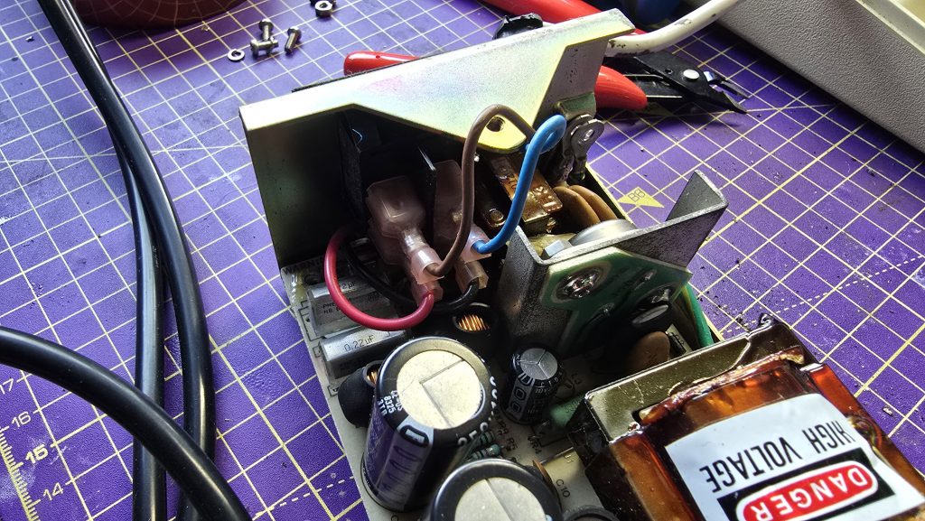
With that job done, I re-assembled the computer and started the standard troubleshooting process.

The first test was checking the voltages, both the +5v and -5v rails were within tolerance , so no issues there. The next step was to check the clock signal.

The BBC has a 16Mhz crystal oscillator which feeds into the BBCs video ULA. The ULA then takes this clock and divides it into multiple clocks for different parts of the system. The outputs run at 1Mhz, 2Mhz, 4Mhz and 8Mhz. Or at least they should! Checking these pins on the Video ULA showed that only the 1Mhz clock was running and the others were all dead.

Unfortunately, this is far from ideal as this is a custom chip and not a cheap one to replace. But since I had a fully working BBC Model B on the shelf, I was able to borrow the video ULA from that to see if the problem would be resolved.

It was never going to be that easy though was it! The BBC still emitted the same failure tone. But there was one change, and that was we now had clock signals and could see activity on the address and data bus, so at least we were trying to execute code now.

Since signals were looking ok now on the CPU, I figured memory chips may be the next issue. There is a little trick you can do on the BBC where you change jumper 25 (I think?) from position 1-2 to 2-3 and this makes the BBC think it is a 16K machine. If the machine boots in this config, then you know there is faulty memory in the upper half of the RAM.

This configuration didn’t work for me either, so if there is a memory fault, it’s within the lower 16k or in the lower and upper 16k if there are multiple failures.

The next step was to grab my thermal camera and see if anything was obvious. With this, I spotted two of the RAM chips were stone cold whilst the others were nice and warm. Starting with these two, I removed them from the board and tested them in my RAM tester. This confirmed that both of these chips were dead. So, I put two sockets in and placed two new chips in the sockets.

Another power on test revealed we still have the same problem. It was time to face the hard truth, any one of these chips or combination of them could be faulty. So I set about removing them all from the board, testing them and fitting sockets in their place.
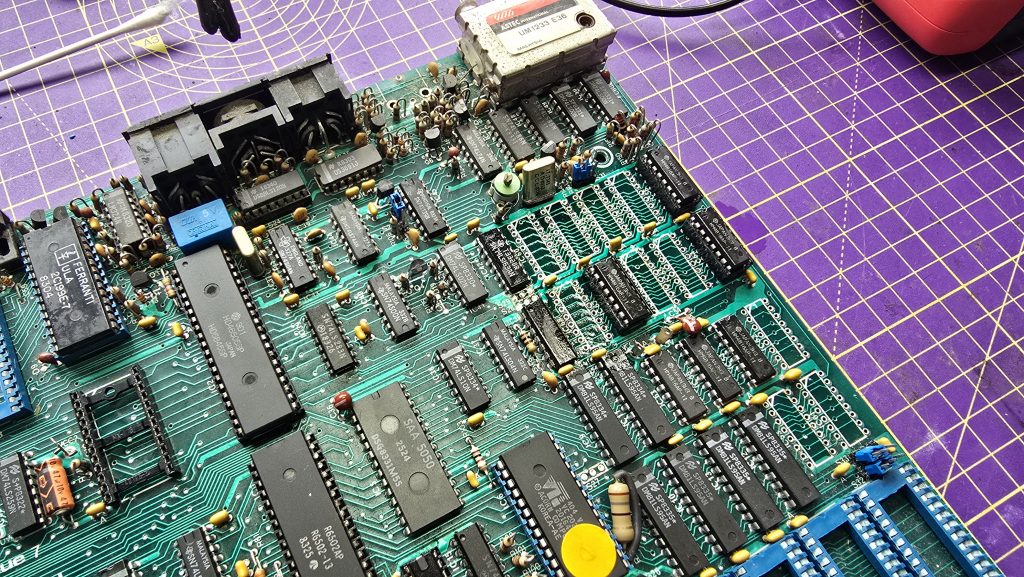
Tedious work, but eventually I had a board fully fitted with RAM sockets and a full test of verified RAM chips. A total of 5 RAM chips tested faulty.

With my fingers crossed, I power it up for another test. This time I got the normal startup beep! Could it be that we finally have a working computer? It was time to move the BBC over to my Cub monitor and see what we get.
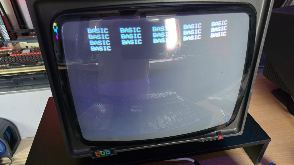
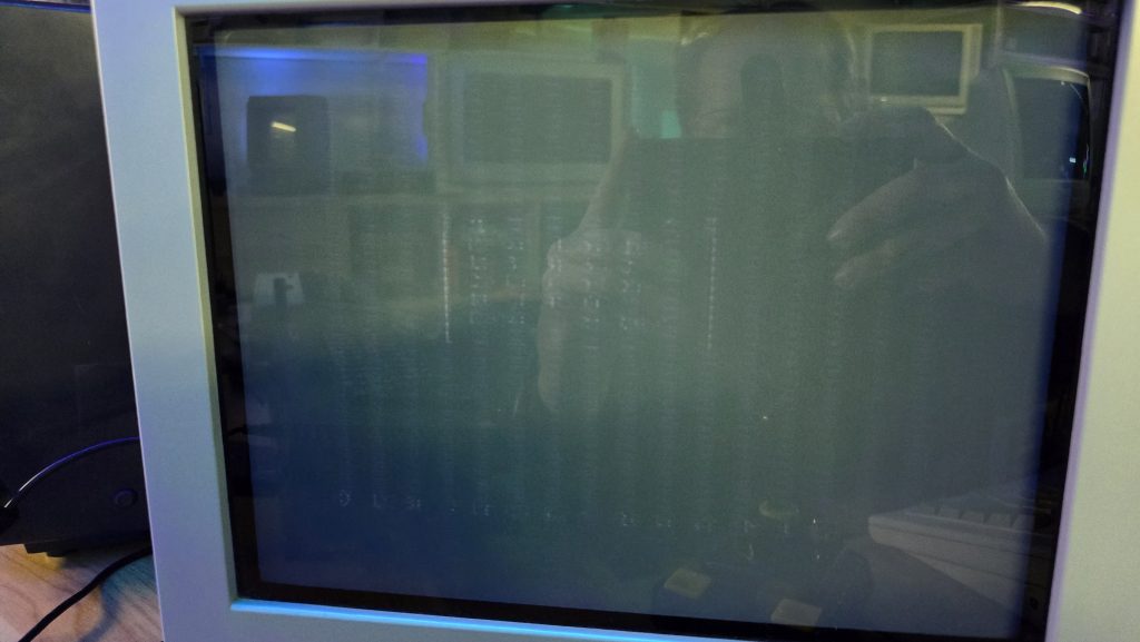
Erm, well lets call that progress at least. But this is not what I would expect from a working computer.

Every now and then I like to test out AI’s skills on repairing vintage electronics. So I gave it a detailed explaination of what I was seeing and it assured me 100% that I had faulty RAM chips. I told it that it was 100% wrong and that my experience showed that when you get weird repeating pattern things like this, it’s normally an addressing issue. It told me that I was 100% wrong, so I completely ignored it and started troubleshooting my addressing issue 🙂

I went back to the schematics and looked up which ICs sat between the RAM chips and the CPU.
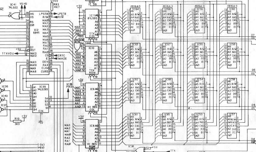
As you can see, the address lines from the RAM chips all connect via IC 8,9,10 and 11 to the 6845 CRT Controller chip.

I went through all of the A0-A6 lines on each of the chips which all appeared to have good looking activity. But when I tested the MA lines on the left side of the chip, I noticed a few of them were just floating.

I made a note of which ones were missing across all of the chips and found that lines MA3,MA4,MA5 and MA6 were all suspect. I checked these signals on the 6845 chip and saw the same issue there. Since these were outputs from the 6845, I suspected another faulty IC, so I grabbed the one from my working computer and put it in place.

Another power on test, and…….
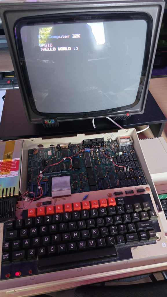
We finally have a working BBC Model B!

I still need to do some final checks on this one and make sure it can load software from the cassette port (It’s never had a disk drive fitted so doesn’t have the DFS Rom fitted).

Once I’ve done these remaining tests I’ll be putting it back together, giving it a good clean and then this one will also be going up for sale. It is missing the clear plastic strip that goes across the top of the keyboard, but apart from that it’s in pretty clean condition. These strips can be picked up off ebay occasionally, but I’ve already spent too much on this repair, mainly due to the Video ULA which cost £45 on it’s own. There was then the 6845 at £12.25 and 5 memory chips at £12.50 making the total cost of repair on this one £69.75.

Was it worth it? Including my time if I was to charge labour, then probably not. But this isn’t about making me any money and I’m not charging any labour on these repairs. A BBC Model B lives to see another day, and any profit from the sale will be going straight to my friends wife and his family.

So, if you are interested in getting your hands on a BBC, then keep an eye on my shop. I’ll also be listing on eBay for people more comfortable purchasing that way, but the cost will be slightly higher on eBay.

The next computers to look at are some C64’s. Will they work? Stay tuned to find out 🙂
Posted on Leave a comment

Atari 800XL Repair

A few weeks back, I went and picked up a bunch of computer systems that used to belong to a friend of mine. To help out his family, I said that I would test them all out and then look to sell them on their behalf.

The first of the systems I looked at was a fully boxed Atari 800XL. This was complete with its power supply, manual, boxed tape recorder and a few games.

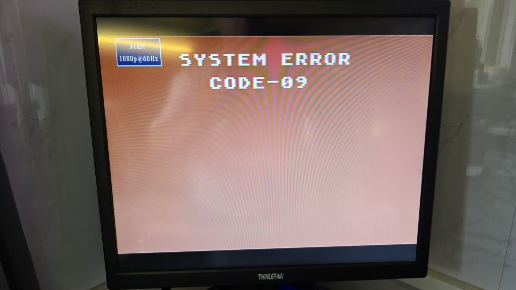
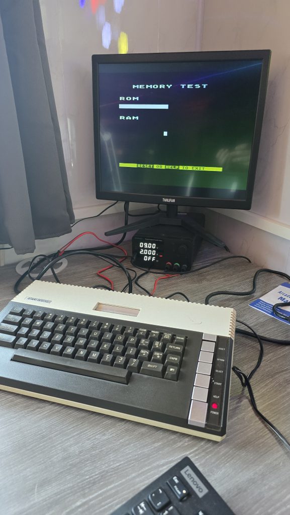
Connecting the computer up for the first time confirmed that this unit was going to need a repair. The unit booted straight into the ROM/RAM test screen without having the option key pressed.

For those that don’t know, if you hold the option key when turning on an old Atari, it will go into a self-diagnostics mode where you can test the ROM/RAM/sound and keyboard.

The issue that now presented itself was that the ROM/RAM test was not actually running, and the screen just stayed stuck showing the screen above.

In my tool kit, I also own an Atari SuperSALT Diagnostic cartridge, so the next step was to give that a go.

Well, that was helpful wasn’t it! I couldn’t find any reference to this error anywhere, so I think roughly translated, it is saying your computer is broken and needs to be fixed!

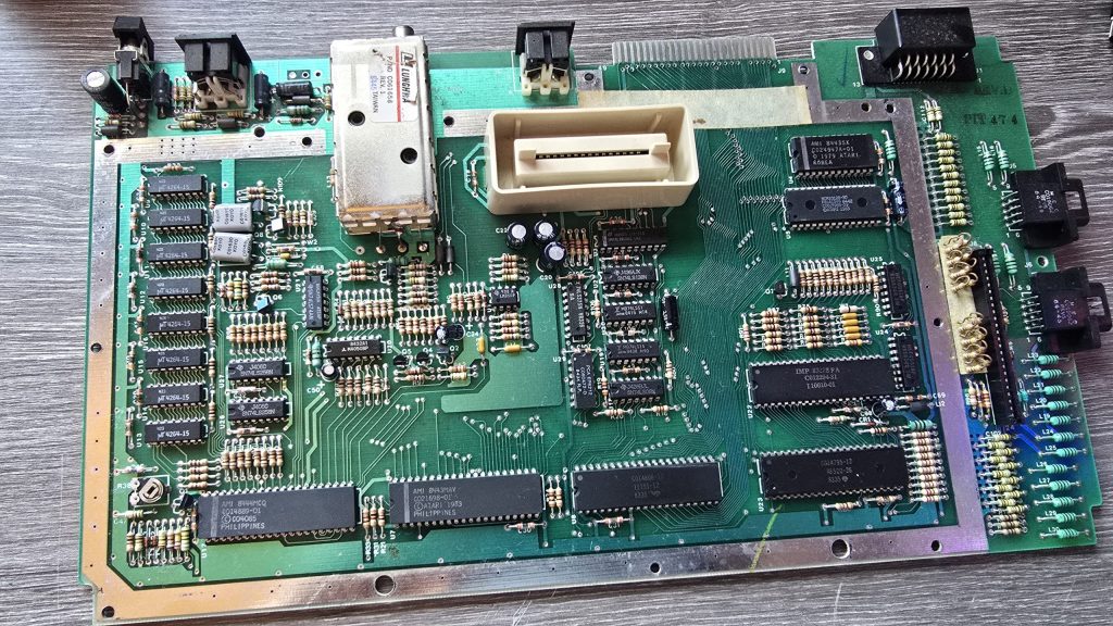
Time to take the computer apart and see if we can see what is going on.

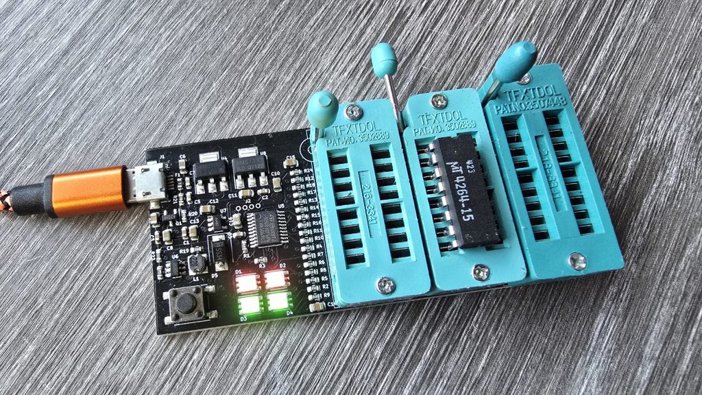
Everything is looking clean in here, but the first thing I spotted was MT branded RAM. This is known to fail, so at this point, I would put my money on that being the issue. But before we jump the gun, I tested the voltages, the reset signal, the clock signal and then scanned down all the address bus and data bus pins. All of these signals looked good, so it was time to start removing RAM chips.

I started at the top, unsoldering the chip, fitting a socket and then testing it in my RAM tester. If the RAM chip was bad, I put a new one in its place and then tested the computer again to see if anything had changed.

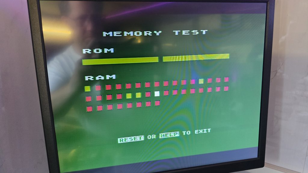
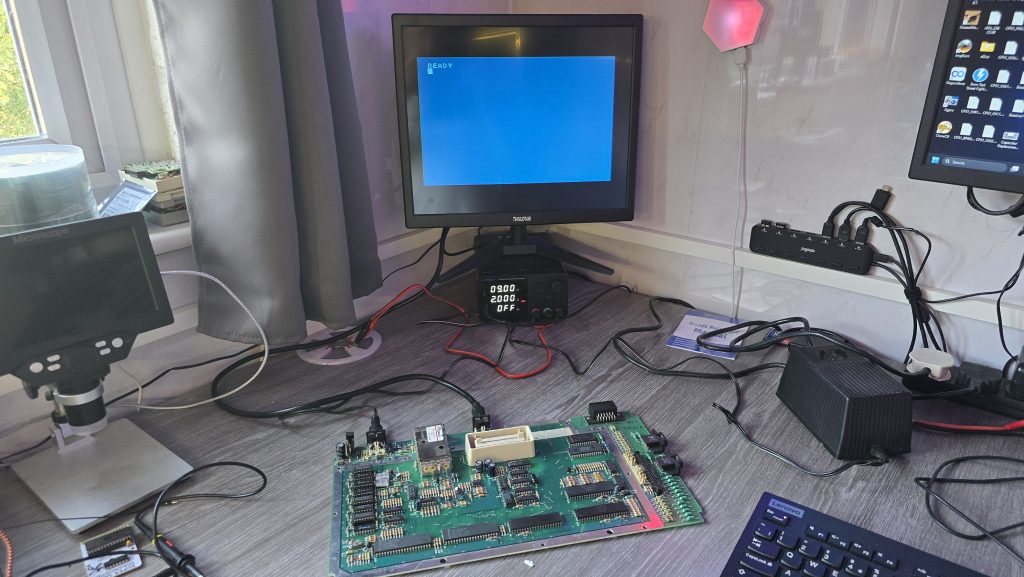
After replacing the first failed RAM chip, the computer was powered on again, and this time the ROM tests passed. The memory test ran but failed significantly. At least we are on the right track though!

I did a look around, but I couldn’t find any reference as to how the red dots above related to the physical RAM chips. So, apart from it indicating that there is a RAM failure still, it wasn’t of much use.

So I continued running down the chips, and after replacing the second-to-last chip, I powered on the computer and was greeted by a nice blue screen with the ready prompt.

I rebooted the computer and held the option key this time to force diagnostics mode and confirmed that the RAM test now ran all the way through.

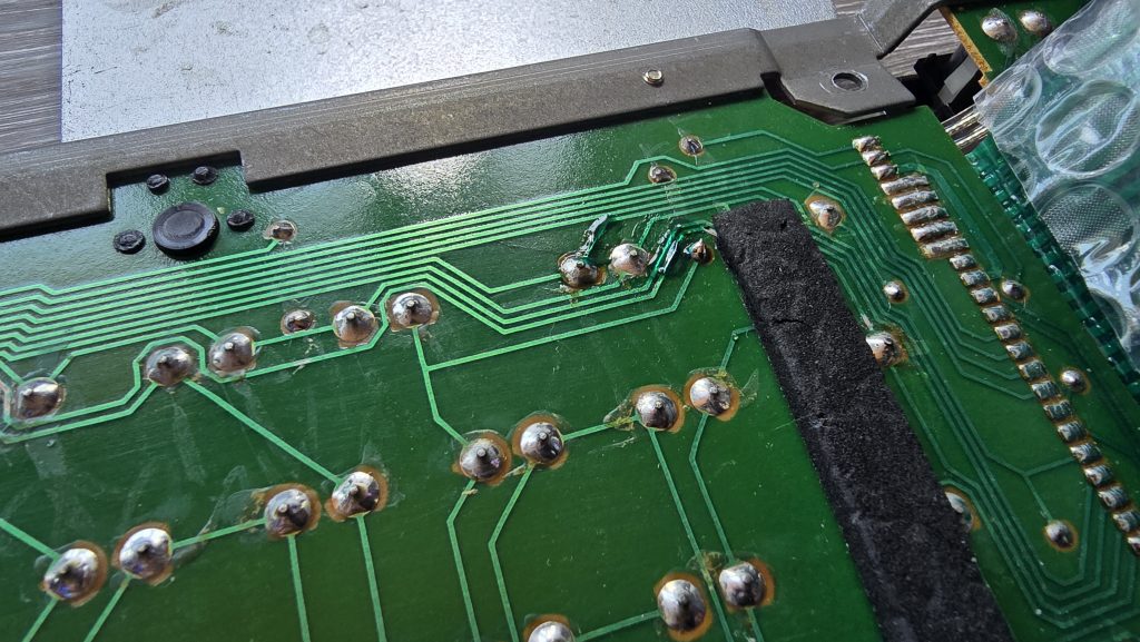
I then moved on to the sound test, which passed, and finally the keyboard test. But here we hit our next issue. Keys ASDFGH are not working. I checked the ribbon cable and put some de-oxit in the socket, but this didn’t help.

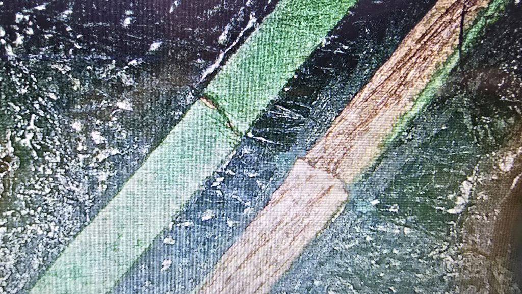
I checked the traces from these keys to find which trace was common between them all, then with my multimeter in continuity mode, I followed the trace and worked out the rough area where the connection was broken. The odd thing was, it actually looked fine. So it was time to give my ageing eyes a rest and drag out the microscope.

There you are, the tiniest of cracks on the PCB. I’ll forgive myself for not seeing this without the microscope! A quick repair job later, and continuity has been restored.

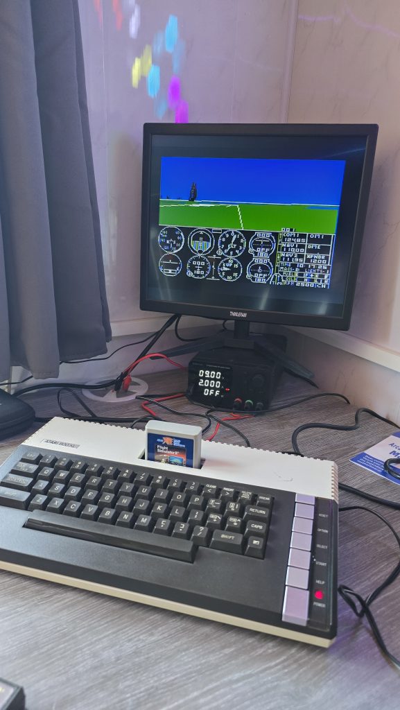
A quick final test of the machine reveals we now have a fully working Atari 800XL.

So, the only things wrong with the machine in the end were 4 RAM chips and a small crack on the keyboard PCB. The total cost of the repair was around £13 for the RAM chips.

I will now clean the computer up and test the tape drive and the games. If everything is good, then this machine will be going up for sale soon. I’ll probably list it on eBay, but will also add it to the shop on this site with a slightly lower price if anyone wants to pick it up.

I’ve also listed some new old stock joysticks on my shop, so if you want an Atari/Commodore Joystick, be sure to check that out.

My next repair will be the BBC Model B, which just powers on with a long continuous beep. Stay tuned!

Posted on Leave a comment

I bought a box for £130 😬

Quite a while ago, I realised that collecting computers/consoles with their original boxes came with one big downside, the amount of space they take up!

I have a lot of boxes for a lot of systems, but I don’t really have the space to display all the boxes. The majority of them spend their time sitting up in the loft, which seems pretty pointless.

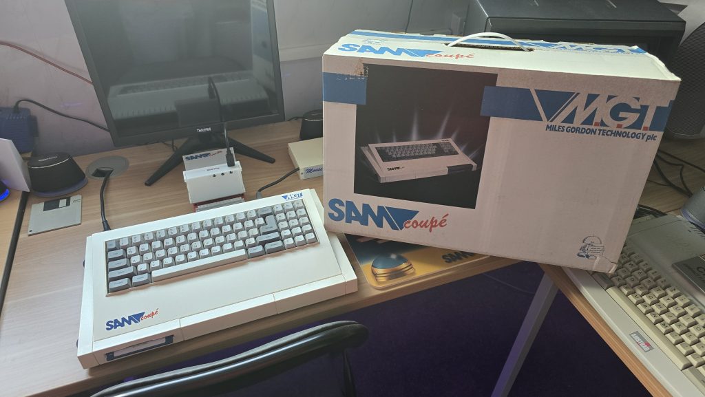
But when one specific box came up for sale recently, I knew I just had to get this one as it holds a special place in my heart. I am of course, talking about the Sam Coupe box.

Despite having 3 of these computers here, the boxes for them are long gone. At least the computers themselves never got thrown out!

I have only ever seen an empty box go up for sale once before, and that was a few years ago now. Usually, the boxes only sell with a computer inside, and these tend to fetch ~£1500 these days. So I had to grab this one whilst I could.

The box is in pretty good shape, complete with all the internal polys, and the blue bag that the computer was originally wrapped in.

I look forward to fully packaging up one of my Sams now with all of the original components, where it can sit out on display alongside my daily driver Sam.

Let this be a lesson to everyone, collecting boxes can turn into an expensive hobby! 😅

Posted on Leave a comment

HP Jornada 720 added

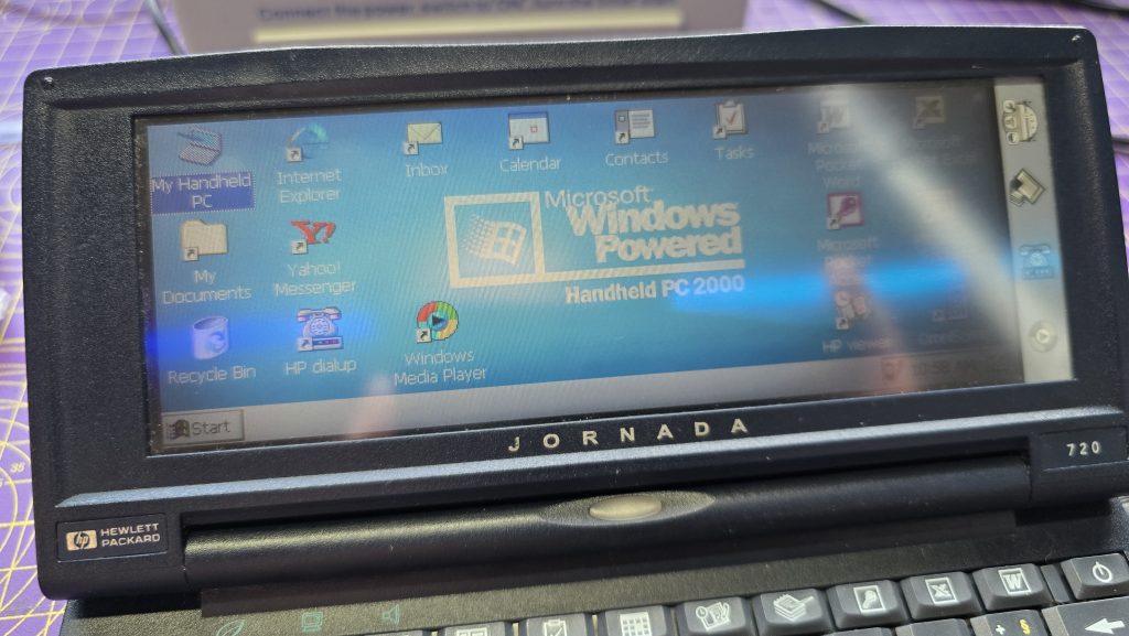
For some time now, I’ve had the HP Jornada 720 sat in my watch list on eBay. Last week, one popped up with my favourite word in the title, “FAULTY”.

The description said the device was all working apart from the keyboard. This was either going to be an easy repair or something a lot more difficult. I decided to take a chance and made an offer on the device, which was accepted.

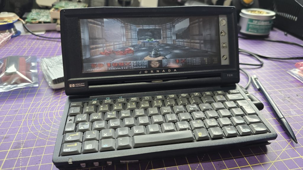
Upon receiving the device, the description was accurate. They said that it was never opened, which was confirmed by the warranty sticker still being intact. I opened it up, pulled the keyboard ribbon cable out and gave it a clean with some IPA. I then connected it back up, and everything is now fully working.

A nice and simple repair, and now I have a fully working device to play around with.

And yes, it does run Doom!

Posted on Leave a comment

Impromptu Toastrack Repair

Every now and again I like to have a move around in my retro room and possibly swap out some systems. Well I decided that to represent the Spectrum, I would get one of my 128K Spectrums connected up. I grabbed one off the shelf and plugged it all in ready to sit down and have a play. Only to find out, this one had become faulty!

When turning it on using the RGB scart cable, the picture was pretty much black. But this wasn’t a dead Spectrum, as if you looked closely you could see that the computer itself was running fine.

It’s not very clear in the picture but in the center of the screen you can just make out the 128k menu.

This then was more of an issue with the video signal, specifically the blanking signal on the scart cable. Just to rule out a bad cable I tested my other toastrack and that displayed fine.

There is sometimes an issue with Spectrums and certain TVs when using the RGB scart cable, and there is a quick mod you can do to increase the blanking voltage which helps in this situation. But I didn’t think that was what was going on here, and I was pretty sure I had already done that mod on this system at some point.

I opened it up and checked the blanking voltage which was at 1.45v. Yeah, there is something not happy here. Another common fault with these machines which would match the issue I was seeing, is the two transistors, TR4 and TR5.

Taking TR4 off the board and giving it a test, confirmed my suspicions.

That doesn’t look much like a transistor to me! So, a quick trip to eBay and a few days waiting for some replacements to arrive.

I did test TR5, and it actually tested OK. But I replaced it anyway to be safe. Sometimes, if you only replace TR4, TR5 can end up damaging the new replacement.

Anyway, we are now back to having a decent voltage on the blanking circuit, and yes, I had already done the blanking mod on this one.

Time to put it back together and give it a test!

All working 😀

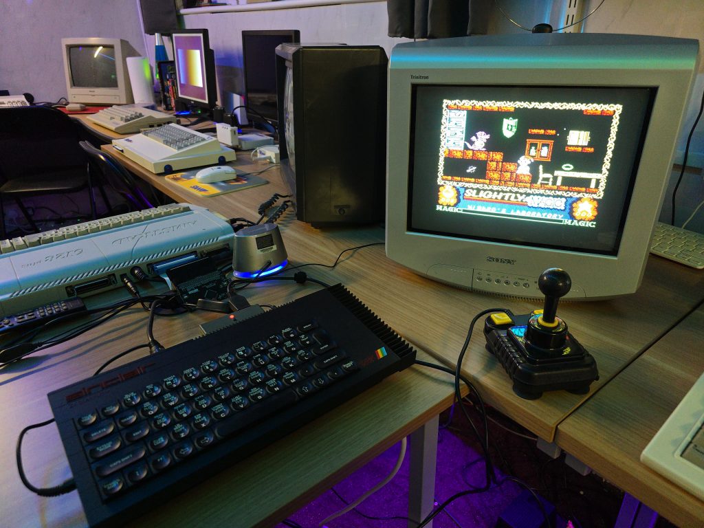
Unfortunately, that used up my spare time this evening, so i don’t actually get to sit down and play a game. Slightly, will have to put his adventure on hold until next time.

Posted on 1 Comment

Spectrum 48K Repair

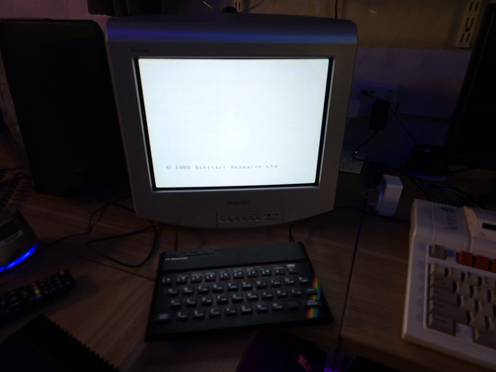
Today I had a bit of spare time, so decided to take a look at a Spectrum 48K for one of my work colleagues. It had unfortunately been plugged in using an Acorn Electron PSU as he mixed up the power supplies.

The Acorn Electron uses a 19v ac power supply, where as the Spectrum uses a 9V DC supply. As you can imagine, the poor Speccy did not appreciate this very much.

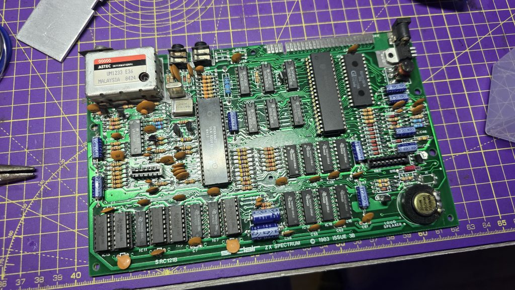
First job was to check the voltage regulator. As expected, this was dead, so I swapped this out with a new 7805 regulator. Now we were getting a stable 5v output from the regulator.

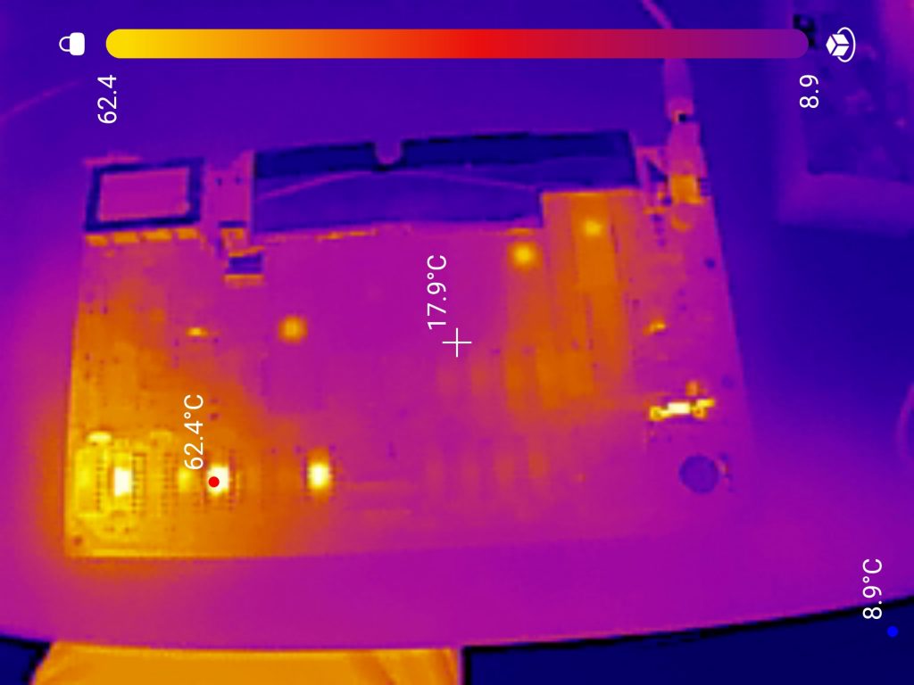
Next step was to dig out the thermal camera and see what the system looked like powered up, I didn’t hook it up to a TV yet as I was pretty confident there were more issues I would need to solve first.

I forgot to take a photo the frist time around, so the photo above is after I had already replaced the far left RAM chip which was also getting very hot.

There were 5 chips in total that were getting pretty toasty. I socketed all of these and tested the removed chips, all of which tested faulty.

With the new RAM in place, I figured it was time to test the machine out. Even though no chips were getting hot now, some more of the RAM could have still been faulty.

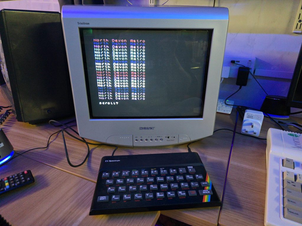
Luckily, In this case, that was not the case and the Speccy booted up, seemingly with no issues. I wrote a little BASIC program just to make sure it was executing code.

So far so good, but I wanted to test some games out. At this point I grabbed my DivMMC device and hooked it up. But here we ran into another issue. The DivMMC was not showing any life when connected to this computer. From previous experience I knew that the M1 line on the CPU can stop the DivMMC from working if it doesn’t function properly. And sure enough, I probed pin 27 on the Z80 and it was just sat there at around 2V, not doing anything.

Fortunately, I had some spare Z80s in stock, so i removed the Z80, and fitted a socket along with the replacement Z80.

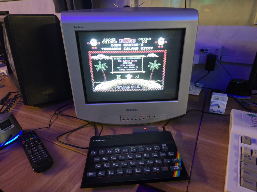
Finally we have a fully functional Spectrum again 😀

Posted on 1 Comment

An ambitious and not 100% successful repair attempt – Epson HX20 LCD Board rebuild

I decided I wanted to pick up an Epson HX20. The fact that it has a built-in dot matrix printer seemed like it would be a pretty cool thing to mess around with.

After a bit of research, I discovered the main issue is that they came with a Ni-Cad battery installed, which usually leaks and causes damage to the computer. But a bad trace or two should be a simple enough fix, right?

So I trawled eBay and found a spares and repair unit for a cheap price. After all, I didn’t want to spend much on a computer that has a high chance of not working. And the majority of these computers are sold as untested or spares and repairs for that very reason.

Well, the device turned up, and upon unpacking it, I could already smell the leaking battery, but this was expected, so I took it apart to check out the LCD board, which normally takes most of the damage. I gave it a quick inspection to see if any damage was visible. And, well, yes, there was some visible damage lol.

From what I could see, a large number of traces were destroyed. So let this be a warning to anyone who is going to take a chance on one of these, if it’s “untested”, this is probably the state of it!

I downloaded the schematics and started testing the connections and marking off which ones were not connected. After a while of doing this, it became apparent that this board was pretty much destroyed. But I didn’t instantly give up (Although I probably should have).

I wanted to try one other thing: could I actually remake the board from scratch? This was a very ambitious project, and I didn’t really hold out much hope, but I think on the first attempt, I actually got a lot further than I expected.

I spent quite some time designing the PCB and re-creating some of the components in Easy EDA, as they weren’t in any of the libraries. The LCD screen for example, needed to be measured precisely and drawn manually.

Eventually, I ended up with this:

I had to manually route quite a lot of the connections, as the auto routers just couldn’t work it out, even on a 4-layer PCB.

But eventually, I ended up with a PCB that said all traces were connected. So I took the plunge and placed an order with JLCPCB. When they arrived, I then had the next challenge of unsoldering all the original parts and re-fitting them to my new PCB.

It was then time to give it a test. Would I see anything? Would lots of smoke pour from the display?

Well, to my surprise, it actually kind of worked. The main issue I had though, was that the alignment and fitment of the LCD screen wasn’t perfect, and I think the pin spacing was also very slightly out.

So, to be fair, I think I did a pretty good job and probably went above and beyond what anyone else would do to try and recover one of these computers.

I have proved that the actual computer itself is working fine, but I didn’t test the printer or tape drive on this unit. Now I have one of the boards made up, which I can directly compare against the original board, I can see some errors that if corrected, may actually get this working again 100%.

The problem is, changing these parts means a complete re-route of all the PCB traces again, which was quite time-consuming the first time around.

For now, I took the coward’s way out and purchased another HX20, which is nearly fully working and the only issue is with the cassette drive, which I think I can handle! I also tested the expansion unit from the old machine and tested it with the new one, so confirmed that it works fine.

So here is the new machine in all it’s glory!

I think I may give the LCD board another go, as it would probably be useful to the community to recover from this common fault on the HX20s. But, I also think I may take a break for a little while first, as my dreams have been haunted by routing PCB traces

Posted on Leave a comment

Amstrad 6128 Plus

Another recent purchase was this Amstrad 6128 plus. The only thing that was described as being wrong with this one was the disk drive not working properly. I first replaced the drive belt as these are a very common failure point. This got it mostly working but it still seemed to be struggling to read some of my disks. So I hooked up the scope and just tweaked the stepper motor alignment and now it is working spot on.

Next step will be to give it a bit of a clean and then I think this version of the Amstard is going to take up one of my permanent setup spaces, as I don’t currently have an Amstrad computer out on display to easily play around with. So I will get the M4 board hooked up to this one.

Quite an easy repair on this one, but happy to have a working example in my collection.

Posted on Leave a comment

Atari 400 repair

The Atari 8 bit computers have always been a bit of a mystery to me. I never owned one myself when i was younger, and only ever got to play on an Atari XEGS a couple of times at a friends house. I have a few different ones now but I didnt have an Atari 400. So when one popped up for sale at a good price, and with my new favourite words, faulty – spares or repairs, I jumped at the chance.

True to the description, when I powered on the unit, all I got was a red screen. I started with all the normal checks, were the power levels correct? Was the reset circuit working? Do I have a clock signal, and do the data bus and address bus lines look ok?

All of these checks appeared to be fine, so that always makes the repair slightly more difficult. Since I have a few other Atari’s I decided just to try swapping over the CPU and Pokey chips as they can fail. Both checked out fine so I marked them with a nice little tick just to remind myself in case I ever started second guessing the fault.

Now seemed like a good time to bust out my thermal camera, annoyingly I forgot to take a photo of this, but I noticed that one of the ROM chips was getting a lot hotter than the other two. I did a bit of reading up and found the Atari 400 has 3 ROM chips, The first 2 contain the OS ROM which are 4k each, then the 3rd contain an FPP (Floating Point Package) ROM which is 2K. This was the chip that was getting pretty toasty.

Concentrating on this chip now, I started looking on the oscilloscope and noticed that although in my first test the data bus and address bus looked fine, what I was now seeing was when the computer is first turned on, the data bus was held high across all pins for a few seconds and then faded down to normal activity. Something very strange going on!

To see if the FPP chip was causing this weird behaviour, I pulled it out and turned on the computer once more and was pretty shocked to see the following screen.

So it was alive! But how? Since I still had the ROM chip in my hand. Well, it turns out the Atari 400 will actually run fine with the FPP ROM removed, right until it needs to do something with the maths stored in this ROM.

So this was good news. The computer itself appears fine and I just have a faulty ROM chip. The issue now is the Atari uses customised 2316 style ROM chips which are hard to get these days. So I turned my attention to one of the 23xx EPROM adapters which allow you to use an M27C64 in place of the 2316 chip.

I ordered one of these from eBay as I didn’t have any in my parts bin.

Whilst waiting for that to turn up I decided to keep on troubleshooting just in case the ROM chip turned out not to be the issue, but instead maybe the chip select circuit wasn’t working. I actually went down a bit of a rabbit hole on this one, since there were 3 ROM chips, I really wanted to understand how the correct chip got chosen. So I found a copy of the memory map for the Atari. Looked at the memory locations for the OS ROM and the FPP ROM, translated these addresses into binary, and then from that worked out that address line 11 through to 15 were what was being decoded into the chip select lines via a 74LS42, 4 Line BCD to 10 Line Decimal Decoder.

As an example, if the last 5 bits on the address bus were 11011, This would set pin 18 on the FPP ROM chip (One of it’s 3 chip select lines) to high, then pin 21 on the FPP ROM chip to high, then the last 3 bits 011 would go to inputs ABC on the 74LS42, which would cause it to set the final chip select line on the FPP ROM to low. This combination of High High Low is the correct combination to select this specific chip.

I used the same logic above to work out how the Lower and Upper OS ROM chips were selected. This is where I hit a bit of an issue. The schematics I was looking at, combined with the decoding above didn’t add up. There was no way the computer could select the Lower ROM or the Upper ROM by themselves, it would always select both ROM chips.

I was fairly sure my workings out were correct, so I went in search of different schematics for the Atari 400. When I found some, even though they were low quality, I was pleasently suprised to see that the first schematics I was looking at were indeed wrong. For some reason I was pretty happy about this, it meant that I understood how the system worked well enough that I could actually disagree with the schematics that were right in front of me.

Notice on the left picture above that ROM 103 and 104 both have the same Chip Select combination, where as on the slightly blurry image, Pin 21 is Active High on one and Active Low on the other. If you are wondering about the 3rd chip select line, it is actually A11 (I would have to work it out, but I think it is used as a chip select on the FPP ROM but may actually be used as an address line on the OS ROM, something to ponder another day).

After all of that I decided the chip select logic all looked to be fine, and my issue was still likely to be the ROM chip itself.

After a couple of days the 23xx adapter arrived and I spent a long time trying to configure it correctly to emulate the FPP ROM. It took me a lot longer than I care to imagine to realise that the pins on the back, of which you need to bridge two of them, were actually in the order 321 rather than 123 (Why!!!!!), once I had worked that out, I set up the adapter by bridging pins 2-3 on 18,20 and 21. Then bridging 5 as the output pin. I wrote the FPP ROM code to my AT28C64 EEPROM chip, and since this was a 64kbit chip instead of a 16, I repeated the ROM code 4 times to fill the chip (I did try it just at address 0000 but that didn’t work, so remember to do this step).

Finally I was ready to plug in the new ROM chip and when I powered on the computer I was greated with Memo Pad. Now the issue here is Memo Pad actually worked without the FPP ROM installed so I wasn’t really testing anything yet, apart from it wasn’t giving me a red screen.

I happened to have an ATARI SALT Diagnostics cartridge kicking around (Yes I did try this at the start of my repair, but it wouldn’t run with the computer in the state it was in). The good thing about this cartridge is you can just burn an EEPROM and stick it in this cartridge to test ROM files. So I download an Atari BASIC ROM as I had read that this needs the FPP ROM to fucntion.

First test was to pull out my new ROM replacement and try Atari BASIC. It loaded and I got the ready prompt, but then a load of garbage appaeared on the screen and it crashed.

Next I placed my FPP ROM back in the socket, repeated the test and this time I had a fully functioning Atari 400.

All that was left was to re-assemble to computer and feel happy that I’d saved yet another computer and gained a lot more knowledge of the Atari 400 along the journey.

And here it is, The Atari 400!

Posted on 1 Comment

A Quantum Leap! The Sinclair QL

My latest eBay purchase was a Sinclair QL fully boxed with manual, power supply and a bunch of microdrive cartridges. This was again listed as not working so was expecting to do another repair.

When it arrived my first test was to check the voltages coming from the power supply. Nothing seemed to be being output so this was definately one of the issues I needed to sort. I didn’t want to make a start repairing this one yet as I am still working on the MSX2. But I thought I’d just open up the power supply and check for any obvious issues.

It all looked clean inside the PSU, so I plugged it back in to check some of the voltage lines only to find they now all looked fine. I checked the voltages at the connector end again and once again everything looked good.

I can only assume a loose connection at this point so I put it all back together for now. I then plugged the QL in to find it all seemed to be working perfectly. I tested both microdrives and they worked fine also.

The only issue I discovered was the keyboard membrane had a break in one of the tracks. This is a common fault with these old membrane based keyboards and luckily brand new ones are still available so I have ordered one and just need to wait a few days for that to arrive.

So, I think I got another pretty good deal with this one. Bit of a shame that it wasn’t much of a repair as I really enjoy getting stuck into that (The MSX2 repair has been great fun in that respect so will post an update about that shortly).

Anyway, here it is. The Sinclair QL