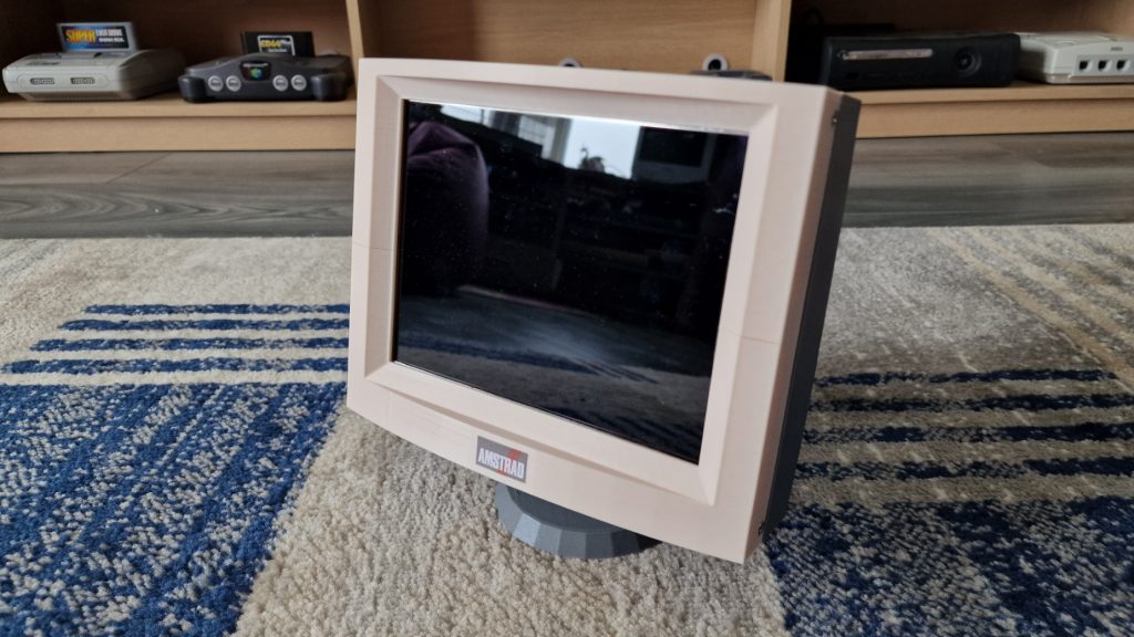
For my Amstrad PPC512, I wanted to use an external monitor rather than replacing the internal LCD green screen. I didn’t have the space for a full-size monitor so I decided to build a mini 8inch CRT replica monitor. The main issue with the PPC512 is it only had CGA graphics, so using a VGA panel wasn’t an option. A little bit more work would be required.
I designed 3D Printed case in Sketchup and then used a combination of off-the-shelf hardware and an RGBtoHDMI board to do the conversion from CGA to HDMI.
The hardware parts I used were as follows:
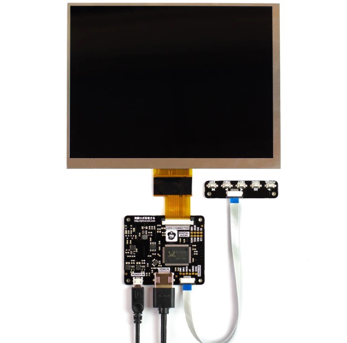
LCD Panel and controller: I used an 8″ IPS LCD panel with a HDMI controller from Pimaroni. Originally I was going to use a cheaper 8inch panel from Aliexpress, but after waiting for a month for delivery, I discovered I had ordered the wrong “kit” and only had the panel delivered without the controller board. So rather than wait another month, I went for the kit from Pimaroni which was a bit more expensive but arrived the next day. Basically, any 8inch LCD screen that accepts a HDMI input should do the job.

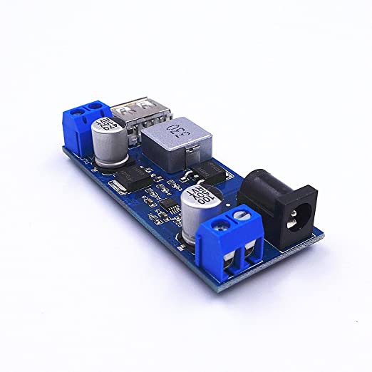
5v step down converter: Because I wanted to power the monitor directly from the Amstrad PPC512 power supply, I needed a step-down voltage converter to take the 13V down to 5V for both the display and the RGBtoHDMI board. For this, I used JZK 24V/12V to 5v 5a Power Buck module from Amazon. This has a standard DC barrel jack onboard which meant I could use a Y-splitter cable from the original Amstrad PSU and connect it to both the Amstrad and the monitor. The output from this module is a USB port so again I used a Y-splitter cable to convert the USB A into two Micro USBs, one of which powers the RGBtoHDMI and the other powers the monitor.

RGBtoHDMI board: This is the main component of this project, The RGBtoHDMI project (Link here) can take the signals from many old computers and convert them to a low latency pixel-perfect HDMI signal. I use this same board in my HDMI Interface for the Sam Coupe. The board connects to a Raspberry Pi Zero and utilises the mini HDMI port on the Pi Zero for its output. So you will also need a short mini HDMI to full-size HDMI cable to link this all together. The only issue with using this board is currently they can be pretty difficult to get hold of due to the component shortage. The Raspberry Pi Zeros are also currently difficult to obtain.

Cables, buttons and connectors: As mentioned above, I also used a few different cables. Namely, a DC barrel jack Y-Splitter, a USB-A to micro USB Y-splitter, a mini HDMI to HDMI cable and a custom made cable is also needed which has a 12-way IDC socket on one end linked to the 9pin Female DB9 socket on the other via a short length of IDC ribbon cable. The wiring for this cable can be found in the assembly instructions below.
I also used a single push bush switch on the back of the monitor to allow you to change the RGBtoHDMI settings without having to open up the monitor case. This requires using the Single Button mode of the RGBtoHDMI board which is described below.

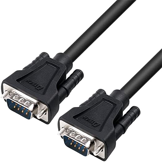
One final cable required was 9pin DB9 Male to 9pin DB9 Male straight-through cable to use as the CGA cable. I found a short one of Amazon which worked fine, but when I tried a 2m cable the colours were messed up, this could have been down to a faulty cable though or the fact the ones I found are advertised as serial cables so may not have the best quality wiring or shielding. Make sure you don’t get a null modem cable which has the pairs of wires crossed over.

Screws: To screw the case together and to fix the tray in place you will need some M3x12mm (6 in total) countersunk machine screws. Also required are 4 screws to fix the RGBtoHDMI board in place, these were M2.5x6mm. Finally, two more countersunk M6*16 machine screws are required for screwing the two sections of the base together.

The next main part is of course the 3D printed case. I designed this case to be 3D printed without the need for any support material. This cuts down the amount of material required to print the case and also the time it takes to print.
The files for the case can be downloaded from HERE
The case is split into 4 separate prints:
The Back: Print this part at 2mm layer height with no supports and no build plate adhesion option (it has what it needs built-in). This is the largest part of the print and will need a 220mm x 220mm built plate. If your printer can’t manage this then I have also included the Sketchup files in the download so you could try making the design a bit smaller, or even slicing it in half so you can glue it together after.
The Front: Because of the amount of support material needed to try and print this part in one piece, I decided to break it into two sections which once printed will slot into each other to complete the part. This means you can print this part at 2mm layer height with no supports. I would recommend using an 8mm brim around this part just to hold the corners down onto the print bed.
The Tray: This is the part that holds the electronics. I have designed this part with the components above in mind so there are areas specifically for them to fit into. Again, the Sketchup file is included in the download if you wanted to use different components. The main reason for this separate tray was again to make this model printable without having to use a load of support material. So once again print at 2mm layer height with no supports and an 8mm brim.
The Stand: This is the base on the monitor and allows you to tilt the monitor to your desired angle. Print with 2mm layer height, no supports and 8mm brim.

Assembly Instructions
Building the cable: Below is the wiring diagram of the cable that connects the RGBtoHDMI board to the 9pin DB9 connector which is used on CGA monitors.
(Wiring diagram coming very soon™)
Once the case is printed. Assemble the two parts that make up the front bezel of the monitor. Next using some double-sided adhesive tape, attach the LCD panel. Using something insulated (double-sided foam tape or similar) attach the LCD panels controller board somewhere to the back of the panel. Make sure it can’t short out as the back of most LCD panels are made of metal.

Next, on the electronics tray, screw down the raspberry pi zero (leave the RGBtoHDMI board unattached at this point otherwise it will be too tall to fit through the hole in the back of the monitor (I should have made the hole taller but I don’t think it would look as good). Fix the 5v voltage converter board in place using either double-sided foam or hot glue (I used hot glue to keep it fixed permanently in place). Fix the DB9 connecter in place with its mounting screws and also screw in the push button, leaving the wires disconnected at this point.
Next, insert the tray into the monitor and screw it into place. You can now connect up all the wires and fix the RGBtoHDMI board on top of the Raspberry Pi Zero.

You can see the two wires from the push button switch are just soldered onto the legs of the menu button on the RGBtoHDMI board (make sure the two wires are soldered onto one of the sides of the push button as the two top pins and the two bottoms pins are each joined together and the switch needs to be placed between them.)
Once the boards are in place you can connect everything up using the USB/HDMI cables and should end up with something looking like this:

Before you screw everything together. Make sure you have inserted a micro SD card into the Pi containing the latest RGBtoHDMI software (instructions and downloads can be found on the RGBtoHDMI site, but basically just download the latest release, extract it and copy it all into the root of a blank FAT32 formatted micro SD Card). Also, make sure you edit the default.txt file which is in the profiles folder and change the single button mode to 1.
You can now screw the front of the monitor onto the back being careful not to trap the cables. Once you have done that, fix the two halves of the stand together and slide it onto the bottom of the monitor. You should hopefully be looking at your completed monitor.


RGBtoHDMI Configuration
There is not really much to do here. Once you have your monitor powered on you can navigate the menus and switch the profile to CGA mode. Depending on your preference you can also enable scanlines which give a CRT effect to the graphics displayed. Personally, I like this look especially on a small screen like we have used here.
For the first time configuration, it may be easier to use the buttons on the RGBtoHDMI board itself to configure the options before you screw it all together. Otherwise, you can navigate using the push button on the back of the monitor. To use this feature you need to edit the default.txt file which can be found inside the profiles folder on the sd card. Near the bottom, you need to change the single button mode to 1.
Once this mode is enabled, you can bring up the menu by long-pressing the button, and then navigate options by short-pressing. Another long press will select the option, then short presses will change the selected option. You’ll figure it out 🙂
