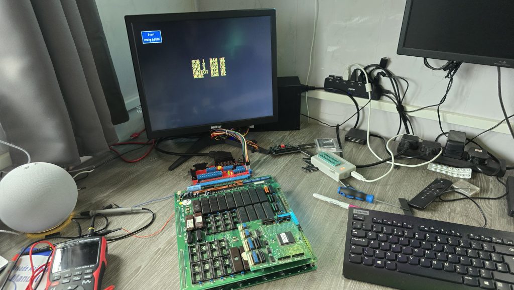
About 1 year ago, I was gifted a couple of arcade boards and an arcade control panel by a friend of mine. Sadly, this friend has recently passed away, so I have now promoted a couple of projects involving these parts to the top of my priority list.
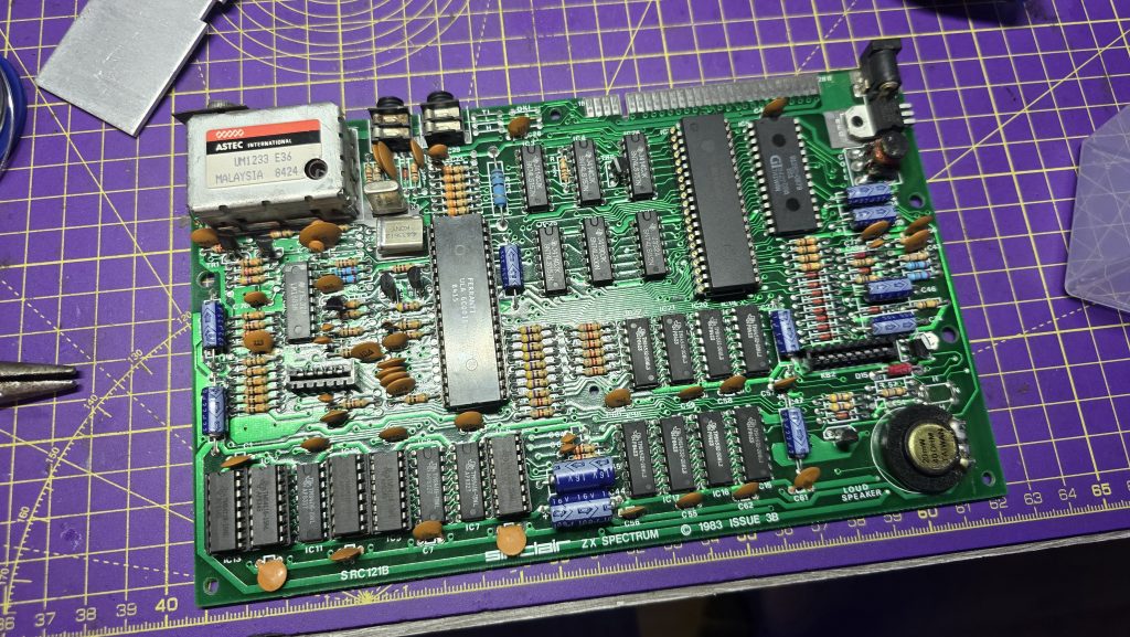
I started by connecting up the two arcade boards (Street Fighter II and Caveman Ninja) to see what we get out of them. The Caveman Ninja board had no output at all, but the Streetfighter II board actually had output to the screen, so I decided to start with this board as I figured it would be the easier repair (Yeah, right!).
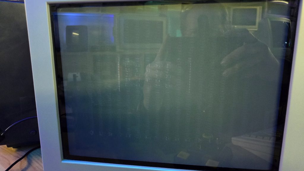
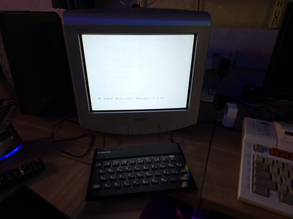
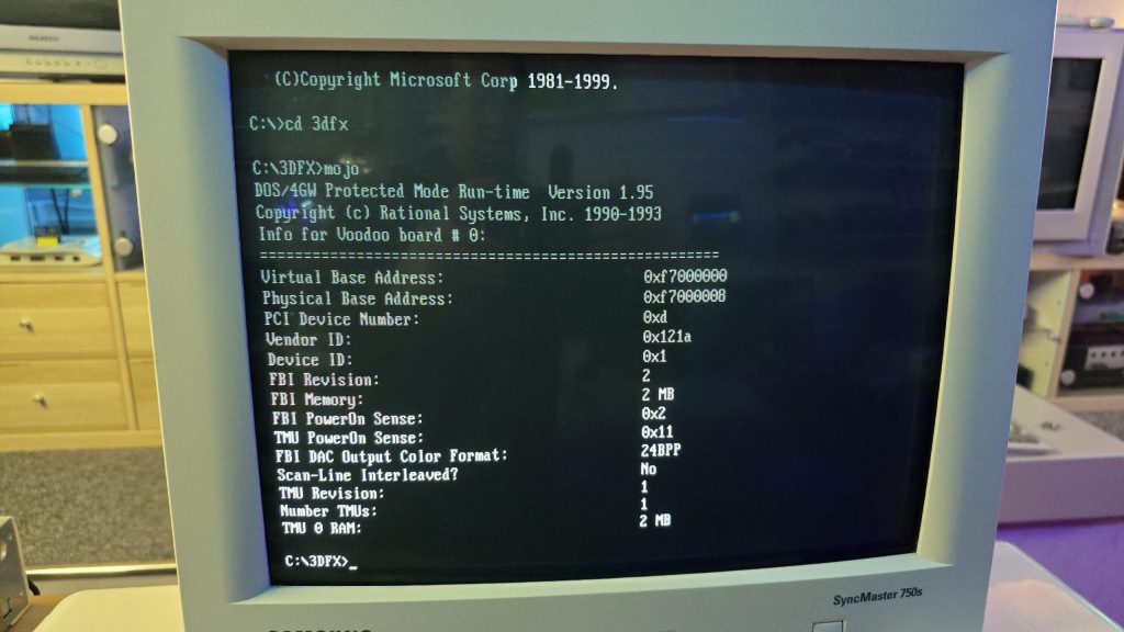
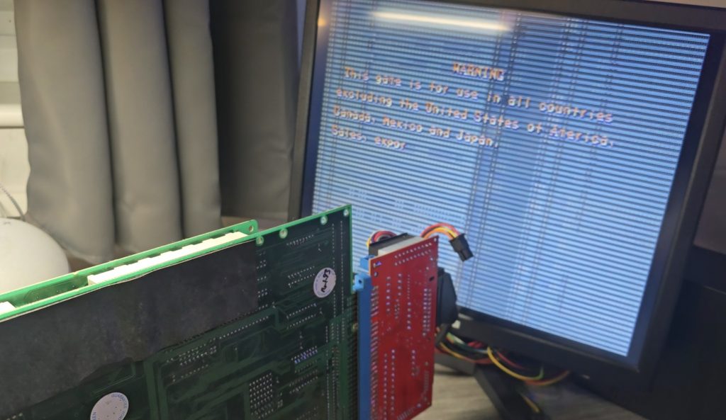
Upon powering up the board, the game ran through the RAM tests, which all passed. But then it just hung on that screen.
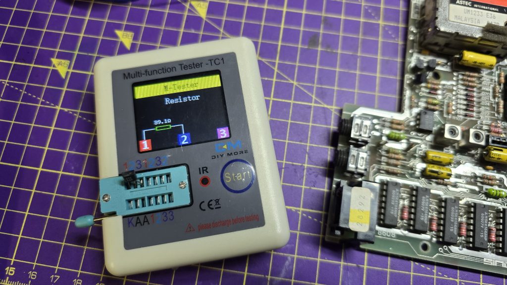
I figured I’d start off with giving the board a good clean up, removing all of the socketed chips, sanding down the pins and giving them all a dose of de-oxit.
The only change in behavior was that the board no longer worked. At this point, I realised my rookie mistake where I had put one of the PAL chips the wrong way around. The writing printed on the chip was upsidedown compared to the others, and I just didn’t check the notch. Very disappointing, but luckily not unrecoverable.
The code for all of the PALs has been reverse-engineered for this board (https://wiki.pldarchive.co.uk/index.php?title=Street_Fighter_2_Champion_Edition), so after I had ordered some GAL16V8s, I programmed one of them with the code and was finally back to square one.
So where do we go from here? Ideally, I need to know what the board is actually trying to do at the point it is crashing. It was at this point that I had an idea. Everybody has surely heard of MAME (Multi Arcade Machine Emulator), which allows you to run Arcade ROMs on many different platforms. However, it also has some advanced features that most people would not have used before, one of which is an internal debugger, which allows you to disassemble the ROM code and also step through the code one instruction at a time, whilst also setting breakpoints and monitoring for specific conditions.
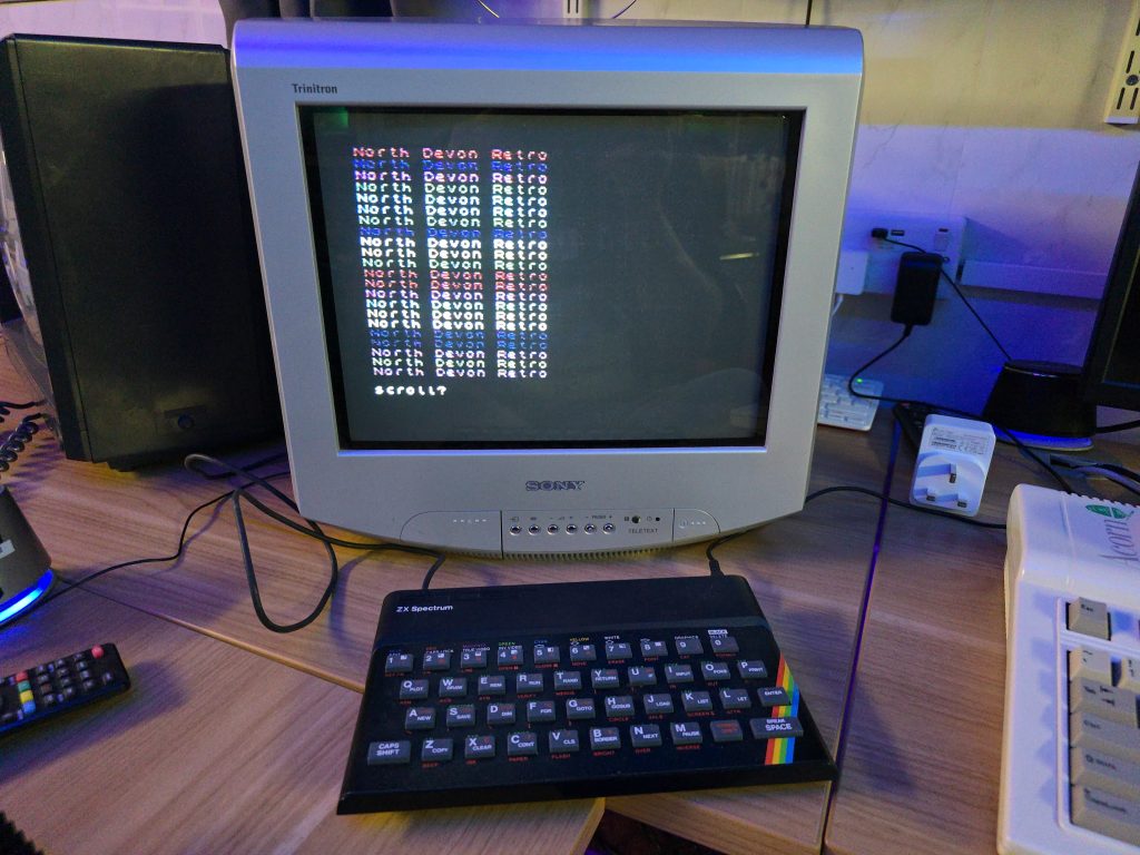
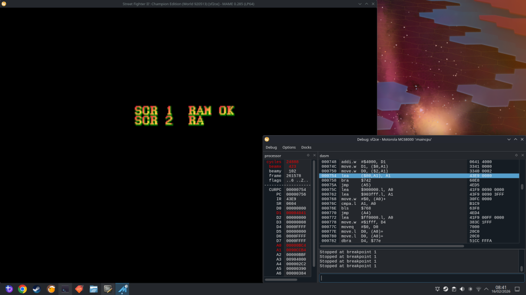
Running the ROM file in MAME, I could see that after the RAM tests, the screen goes blank and then changes the text to Street Fighter II. My board doesn’t get this far, so I needed to concentrate on the code that runs after the last RAM check, but before the screen blanks.
After a bit of playing around, I found a nice breakpoint to set at address 754. This is a loop in the code that prints a character to the screen. So with a breakpoint set here, every time I start the emulator running, it will print one more character to the screen and then pause. This will allow me to step through until the last OK message is written to the screen and then see what happens next.
I could see that during the RAM tests, all it was doing was writing a character into RAM and then reading it back and comparing it. I don’t think this is the most conclusive RAM test, but I guess it’s good enough to find basic RAM issues. I did do a quick check here and manually modified the area of memory so the compare would fail. It responded by marking that RAM test as “NG” (Not Good), and then froze the game. I didn’t need to do this bit as all the tests were passing, but I thought it was interesting.
The next thing I wanted to do was to try to find out where my board was stopping. I had a thought that if I could insert a reboot command into the actual ROM code at various points, I could then burn this to an EPROM and stick it in my board. If my board went into a reboot loop, then I would know that it was getting as far as executing that command.
68000 Assembly is not a speciality of mine, so I used AI to help here (sometimes it does actually have some uses!). My first attempts used a jump instruction to jump to address 0 and reset the board, but this had one small issue in that the opcode was 3 words long (6 bytes). The issue with this is that I could only insert it where another 6-byte opcode existed; otherwise, I would be overwriting other code. Asking AI for another way of rebooting the board, it suggested the opcode “ILLEGAL” which has a hex code of 4AFC. With this being 1 word long, I could insert it anywhere in the ROM without breaking anything.
I gave it a quick test and confirmed that my board did indeed reboot when it hit this command. I continued going through the code in chunks and added my reboot at various points to see how far my code was executing.
I eventually homed in on the exact part of the code where the board was stopping.
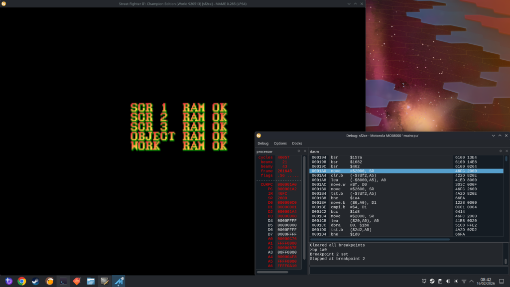
The culprit was an opcode stored at the address 1A0:
MOVE $2000, SR
Giving AI another chance to show its uses. I asked what this command did. It turns out this command essentially changes the Status Registers on the CPU. With the value of $2000, it would achieve the following:
- Set the CPU to Supervisor mode
- Enables interrupts
- Clears all condition flags
- Disabled Trace mode.
Out of those options, I already had a hunch of which one to concentrate on. Going back to the MAME debugger, after the command at 1A0, the next instruction executed was at address 5C6. But there was no jump instruction, so why did it suddenly jump to that address? One logical answer is that an interrupt was triggered.
A bit more research showed that on the 68K CPU, when an interrupt is triggered, it will jump to the address held in the interrupt vector relating to that interrupt. These values are located in the address range 60 to $7C, and looking at that area in the ROM file, I could see 05C6 listed, which confirmed to me that an interrupt was indeed being triggered that was causing the code to jump to address 5C6. The problem now is that my board never triggers that interrupt.
The 68k CPU has 3 interrupt pins, which are inputs. Each one of these can either be high or low, giving us 3 binary bits, and a total of 8 possible combinations.
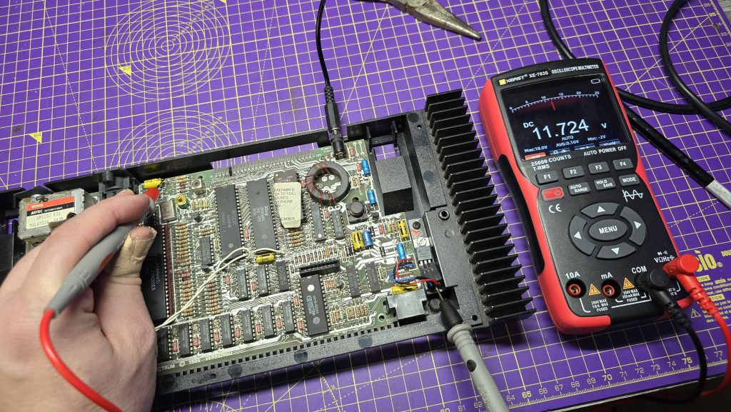
According to the schematics for the CPS1 board, one of these interrupts is tied to 5V, which I confirmed with my scope. That left two other interrupt pins. I monitored both of these on my scope, and both of them remained permanently high.
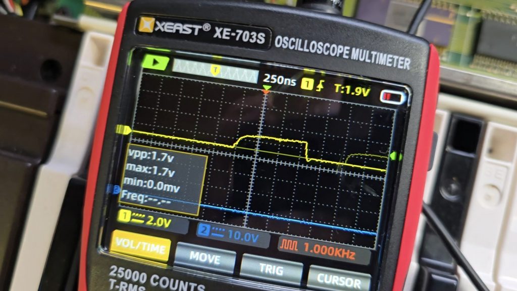
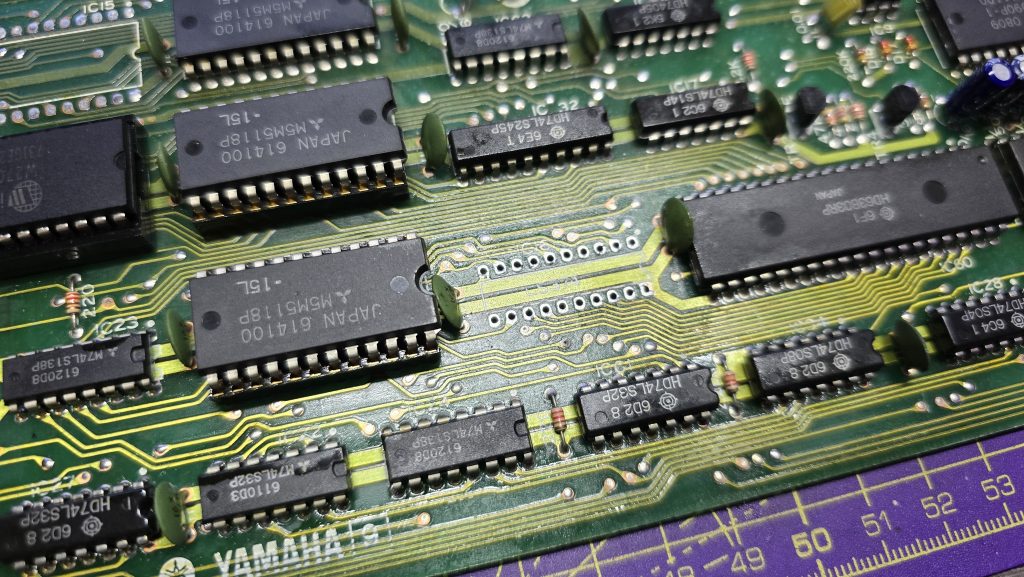
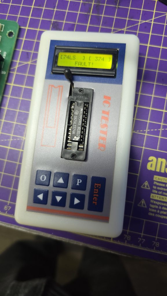
The interrupt signal is an active low signal, so with all these staying high, no interrupt would ever be triggered, and my board would just sit there waiting for this signal. I traced the Interrupt pins on my board back to a 74LS74, which is a dual positive-edge-triggered flip-flop. I took a look at the datasheet for this IC and probed the input pins. One of the pins had a regular pulse to it, and looking at the schematics, this signal was the vertical blank signal.
With this input being triggered, the output pin going to the CPU should also be triggered. So it looks like the first issue to be identified is actually a faulty 74LS chip.
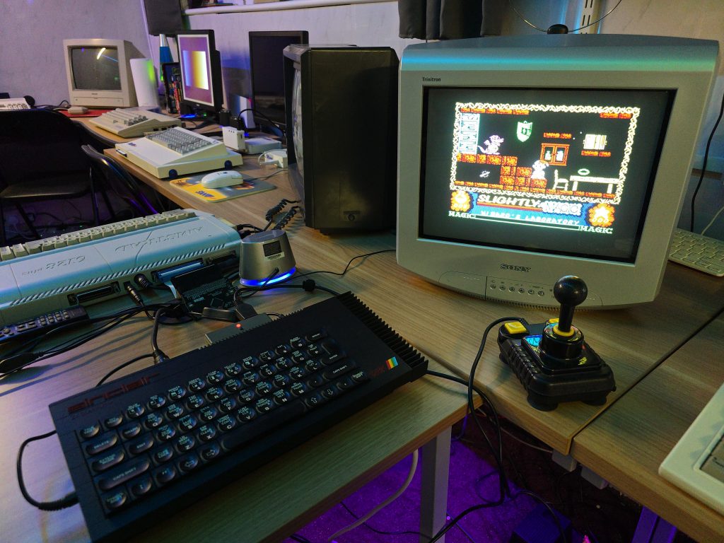
One last thing I could try before wrapping up this part of the repair was to replicate the interrupt being triggered. I could do this by simply shorting this signal to ground. Since the vertical blank signal was a continuous pulse. I replicated this by just tapping a ground wire onto the interrupt pin. With this, I was able to “run” the game frame by frame.
There is another issue in that the background graphics are corrupted. But that will be a problem for another day, after I have got the board at least running the code.
Stay tuned for part 2 once the new 74LS74 chips have arrived