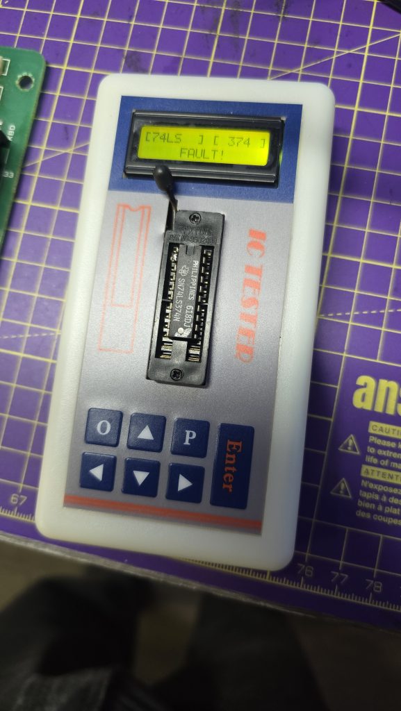
Today was the day that the new 74LS374 arrived in the post. My first quick test was to put the new chip into my chip tester, and it confirmed the chip was ok whulst thebold one still reported faulty, so it looks like the chip tester might actually be trustworthy. I’ll be doing some more testing with this in the future as it could be a very handy tool.
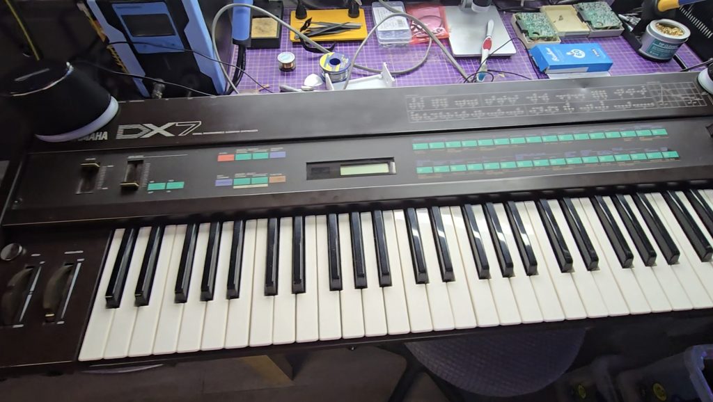
Next step, was to get the new IC fitted and see if the issue was resolved. After powering it on i checked all the address lines and everything looked perfect! The welcome message showed up with no corruption and the DX7 was fully functional again 😀
The only thing left to do was test it out with a talented musician at the keys. Unfortunately I couldn’t find one, so you’ll have to put up with this!
Musical talents aside. I’m pretty happy with this repair, the DX7 is a great piece of music history, and it’s really nice to see it fully functional again.
I can add vintage synthesiser repair to my resume now 🫠
Unfortunately the DX7 has now got to go back to its owner, maybe I need to set up another watch list on eBay 🤔
Recently, a colleague at work contacted me and asked if I wanted some old computer stuff, including a 19″ CRT monitor and a colour Dot Matrix printer. This donation was gladly accepted, and whilst collecting my new toys, we found ourselves discussing various retro tech.
During this conversation, he mentioned that he had a Yamaha DX7 synthesiser that he had purchased, but it had a fault. It is very common for the batteries to die on these, which then leads to corrupted content in the RAM. In this case, though, the battery had already been replaced, but it didn’t fix the issue.
I did a quick Google search for the schematics, and essentially what I saw were the schematics of an 8-bit microcomputer. I said I’d take it back with me and take a look to see what was going wrong. Occasionally, the keyboard would appear to boot up, but would then hang, other times, the display would be garbled and completely unresponsive.
I knew the CPU was trying to run code because the display was occasionally showing correct text. Just to rule out a ROM chip issue, I downloaded the ROM file from the internet and compared it with the ROM stored on this chip. All looked ok, but I wrote the ROM to a new chip anyway and tested with the same result.
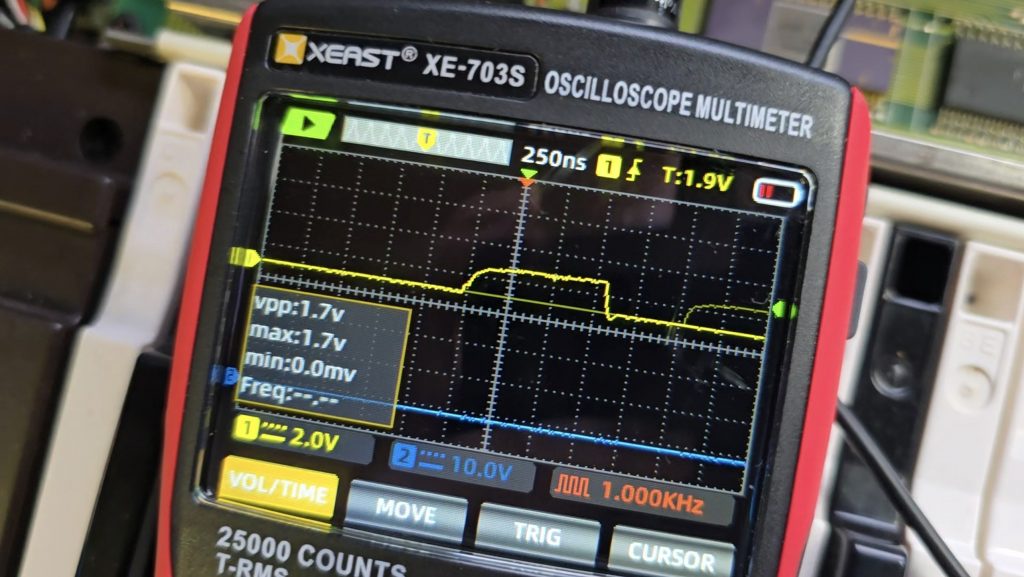
I then grabbed my scope and started probing the pins on the ROM chip to see what the address bus and data buses looked like. It was with the scope that I saw the issue, or at least the first issue. The data bus pins were all looking good with nice strong 5V peak-to-peak signals. But the first 8 address bus pins (0 to 7) were all a lot lower. Address bus pins 8-15 were all working as expected.
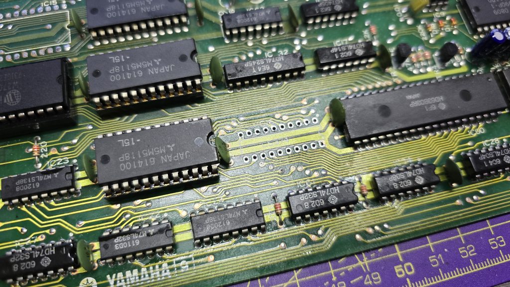
I dragged out the schematics and did a quick glance around for something that was only connected to the first 8 address bus pins. There was one very obvious candidate, a 74LS374 transparent latch IC that sat between the address bus and the ROM chip. Looking at the inputs of this IC showed they were nice and strong with no issues, but all the outputs were low, as shown in the picture above.
I suspected that this chip was faulty, but it could still be another IC on the board pulling the outputs low. So to test for that, I snipped one of the output pins so it was floating, then measured again. Exactly the same issue. At this point, I then removed the IC from the board, ready for the replacement chip to arrive.
Now off the board, I tested the chip in my chip tester just out of curiosity. It did indeed state that the device was faulty. I will be testing the new ones when they arrive, as I’ve not used this chip tester before, so not sure how much trust to put into it yet.
All I need to do now is await the delivery of the new IC and hopefully, this classic synth will be back up and running again. I will of course update everyone with the result, and hopefully this is the only fault 🙂
I already have a few retro PCs in my collection, but I was missing one specific era, and that was the era when the 3dfx VooDoo cards hit the shelves. A friend of mine got one for his pc, and it was a complete game-changer back then. Everything went from blocky-looking textures to gorgeous, smoothed polygons.
The price of VooDoo cards is now quite high, costing around £120 for a working one. But where is the fun in buying a working one when you can buy spares and repairs for a 3rd of the price 🙂
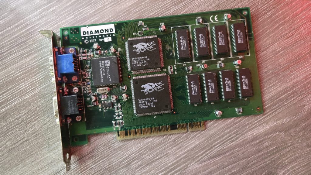
So for 39.99 inc postage, I picked up a Diamond Monster 3D VooDoo card. I had a small concern that the previous owner had admitted to fixing a couple of traces, which meant he had at least attempted to repair this card and had not succeeded. So could I do any better?
I gave the card a quick clean and inspected the traces that he had already repaired. I guess this card was chucked in a box at some point and had gotten scratched. They looked fine, but I re-did them just in case. I also noticed a couple of missing capacitors. There were only decoupling caps, but I replaced those anyway.
The next step was to test it out and see what state it was in. And things were not looking good. I ran the 3DFX diagnostic utility mojo.exe from DOS, and it just hung the system straight after DOS4GW.exe was loaded.
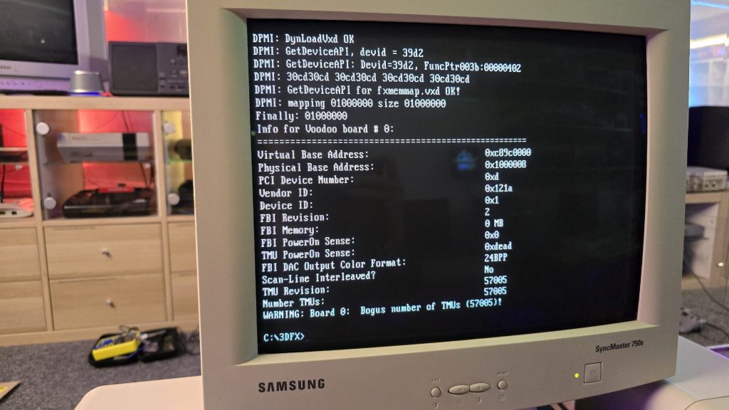
So I then tried booting into Windows 98. Amazingly, it did actually detect the card and installed the driver, but once installed, I got a yellow exclamation mark saying there was a resource conflict. Hmmm, that’s a bit odd. Just as a test, I went into the card settings and changed the memory address to a different one that wasn’t conflicting. I then launched the command prompt from Windows and tried mojo.exe again. This time, I got a different result.
Some noteworthy things here are that it was at least detecting the card now, but no memory on the card and the error code 0xdead didn’t fill me with confidence. The Bogus number of TMUs 57005 error is also hexadecimal for the word DEAD.
The above test gave me some clues, and I started to wonder exactly how a memory space gets assigned to a card when a PC turns on. Without changing the address in Windows, I was still just getting a complete hang in DOS, so it seemed this initial process wasn’t working properly.
I read a whole bunch of docs and figured out that when a PC turns on, the motherboard will probe the IDSEL pins on each PCI slot and communicate with the device on each slot to get the vendor ID and hardware ID. This part must be working, as Windows detected the device.
The next step involved BAR registers (Base Address Registers). This sounded promising. Essentially, each PCI device can have up to 6 BARs. When the card is initialised, these BARs will be queried, and the result of these queries will tell the PC how many chunks of memory space or I/O space the card needs to function. This part of the process is reliant on the PC talking to the card over the PCI address bus. If this process failed, then the card could report that it needs either an incorrect amount of memory or all of it!
At this point, I had already reflowed all the pins on the FBI chip and TMU, as I knew this was a common failure on these cards. But the problem remained, so I needed to check all the address lines. I tried to find a nice picture of the PCI slot pinouts, but since the card doesn’t have all the pins present, it was difficult to work out the pin numbers, so I went with a different approach. Every pin on the 3D X card should in theory, be connected to the FBI chip. So I put my meter on continuity, put one lead on the first PCI card pin and then ran the second along all pins of the FBI chip. As long as I got at least one beep somewhere, I assumed the pin was connected fine.
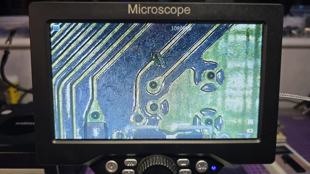
I eventually came across one pin that didn’t seem to be connected to any pin on the FBI chip. So I followed the trace from that pin and found a smoking gun!
Checking continuity between the PCI pin and the via after the break confirmed that there was no continuity. So I carefully scraped away at some of the solder resist and placed a bodge wire across the gap. After confirming connectivity, it was time to do another test.
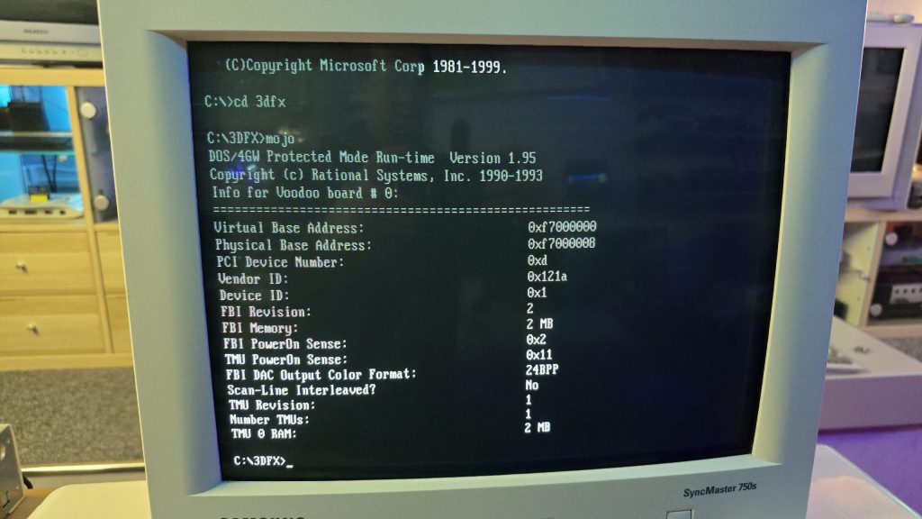
Result!!! After booting directly into DOS and running mojo.exe again, no hanging and everything looked good to go.
So once again, I booted into Windows, this time with no device conflicts. I ran one of the 3DFX demos, and it launched fine, but with one small issue. I could see a pattern of dots on some of the textures.
This was a different fault now, so it was time to move my attention to the TMU chip instead. After carefully inspecting my re-flow work, I noticed the slightest solder bridge between two pins relating to the address bus between the TMU and the memory chips. After clearing this final issue, everything is now working perfectly and I am in possession of a fully working £39.99 VooDoo card.
I decided I wanted to pick up an Epson HX20. The fact that it has a built-in dot matrix printer seemed like it would be a pretty cool thing to mess around with.
After a bit of research, I discovered the main issue is that they came with a Ni-Cad battery installed, which usually leaks and causes damage to the computer. But a bad trace or two should be a simple enough fix, right?
So I trawled eBay and found a spares and repair unit for a cheap price. After all, I didn’t want to spend much on a computer that has a high chance of not working. And the majority of these computers are sold as untested or spares and repairs for that very reason.
Well, the device turned up, and upon unpacking it, I could already smell the leaking battery, but this was expected, so I took it apart to check out the LCD board, which normally takes most of the damage. I gave it a quick inspection to see if any damage was visible. And, well, yes, there was some visible damage lol.
From what I could see, a large number of traces were destroyed. So let this be a warning to anyone who is going to take a chance on one of these, if it’s “untested”, this is probably the state of it!
I downloaded the schematics and started testing the connections and marking off which ones were not connected. After a while of doing this, it became apparent that this board was pretty much destroyed. But I didn’t instantly give up (Although I probably should have).
I wanted to try one other thing: could I actually remake the board from scratch? This was a very ambitious project, and I didn’t really hold out much hope, but I think on the first attempt, I actually got a lot further than I expected.
I spent quite some time designing the PCB and re-creating some of the components in Easy EDA, as they weren’t in any of the libraries. The LCD screen for example, needed to be measured precisely and drawn manually.
Eventually, I ended up with this:
I had to manually route quite a lot of the connections, as the auto routers just couldn’t work it out, even on a 4-layer PCB.
But eventually, I ended up with a PCB that said all traces were connected. So I took the plunge and placed an order with JLCPCB. When they arrived, I then had the next challenge of unsoldering all the original parts and re-fitting them to my new PCB.
It was then time to give it a test. Would I see anything? Would lots of smoke pour from the display?
Well, to my surprise, it actually kind of worked. The main issue I had though, was that the alignment and fitment of the LCD screen wasn’t perfect, and I think the pin spacing was also very slightly out.
So, to be fair, I think I did a pretty good job and probably went above and beyond what anyone else would do to try and recover one of these computers.
I have proved that the actual computer itself is working fine, but I didn’t test the printer or tape drive on this unit. Now I have one of the boards made up, which I can directly compare against the original board, I can see some errors that if corrected, may actually get this working again 100%.
The problem is, changing these parts means a complete re-route of all the PCB traces again, which was quite time-consuming the first time around.
For now, I took the coward’s way out and purchased another HX20, which is nearly fully working and the only issue is with the cassette drive, which I think I can handle! I also tested the expansion unit from the old machine and tested it with the new one, so confirmed that it works fine.
So here is the new machine in all it’s glory!
I think I may give the LCD board another go, as it would probably be useful to the community to recover from this common fault on the HX20s. But, I also think I may take a break for a little while first, as my dreams have been haunted by routing PCB traces
Whilst sat browsing Facebook one day, I saw a post from someone local asking if anyone had a CRT for sale as theirs had broken, and they included a photo of their lovely 28-inch Sony Trinitron TV. I messaged him and asked what the fault was, and apparently the picture went off and was now just blinking the power LED with 2 blinks, which according to the service manual translates as Over Current Protection (OCP) triggered.
I said that if he was going to bin it, then I would like to pick it up and attempt to repair it. After all, you can’t really learn to repair stuff without having some broken ones to fix.
A couple of weeks later, he messaged me to say if I wanted to pick it up, then I could have it. So I got in the car and went and collected it. With some help from the Mrs, we got it home and down into my workshop, where I could then start my testing.
The first thing I needed was lots of information about CRT TVs and exactly how they work. And for this, I highly recommend watching videos by Randy Fromm on YouTube (Start with this one) After watching those, I had a very good understanding of what I was looking for. Even so, this Trinitron turned out to be quite a puzzle.
The first thing I did was test the TV to see what happened when I powered it on. And just as the guy had said, upon powering on, all I got was a blinking power LED flashing twice, then pausing and repeating. The issue with this error code is that it isn’t really very descriptive. Basically something, somewhere in the TV was apparently pulling too much current.
The other thing I noticed was that I wasn’t hearing any high voltage at all. Normally, when you power on a CRT, you will hear a crackling sound from the high-voltage circuit. So I downloaded the service manual for the set and started to look at all of the voltages to start with. This wasn’t that easy, because as soon as the TV detected the overcurrent, it shut down the power supply! Luckily, I have an oscilloscope, and this meant I could visualise the voltage for the very brief moment it was there.
From what I could see, the main voltages were present, specifically the 135V B+ voltage, which would go on to generate the high voltage via the flyback transformer. Another common fault on CRTs is the Horizontal Output Transistor; without this part working, you won’t get any image on the screen, and that part could easily pull too much current if it were to be faulty. But after testing it, it looked fine to me, and on my scope, I could see the required 135V pulses being sent to the flyback. So I really expected to hear some high-voltage crackling when the set powered on.
After looking around, I found that two fusible resistors had blown, which were right next to the flyback. I was hoping that they may have been the cause of the issue. But I wasn’t going to be that lucky, and after replacing the resistors, there was still no life in the set.
At this point, I decided I needed to test or replace the flyback. Unfortunately, I didn’t have any way of testing it at the time. So I looked around and luckily I found a replacement flyback on eBay from Malaysia. The part was new old stock, so I snapped it up and waited for it to arrive.
Fast forward to delivery day, and I swapped the flyback over, held my breath and hit the power button. For a split second, I heard a nice static crackle from the CRT, and then it shut down and sat blinking its LED at me. At least this proved that the flyback was indeed faulty.
The next few weeks were slow and painful. My bedtime reading was the schematics for all the various boards inside the TV. Every now and again, I would have an idea of something to test, so I’d run down, test it and come back to bed depressed that it still wasn’t working.
I went through all of the test points on the CRT and compared the waveforms to what was in the service manual and I just couldn’t find anything wrong.
I then had an idea, a potentially dangerous idea which I don’t think I would recommend to anyone! But I had basically run out of things to try.
The way the Over Current Protection circuit worked, is that it measures the voltage drop across a resistor and if that voltage drop was too high (two much current) it would trigger an OCP line that originates from the power supply board and gets sent to the microprocessor board which would then shut down the TV.
So what if I simply disconnected the OCP wire between the power supply and the processor? It wouldn’t get the OCP signal and would keep the TV running. Maybe then, whatever part was causing the issue would very quickly get hot, and using my thermal camera, I could see where the issue was.
Either that, or it would burst into flames and I wouldn’t need to worry about repairing it anymore 🙂
So, I pulled the OCP wire out of the connector block, pointed my thermal camera at the back of the TV and nervously hit the power button.
And……..
It came on and just worked. I carried on looking around with my camera, but nothing looked wrong. So I left it running for a while and carried on monitoring the situation. After about 20 minutes, everything was still fine, so I powered it off, reconnected the OCP wire and was straight back to a blinking light again.
After scratching my head until I had no hair left, my conclusion was that there wasn’t an overcurrent issue, but actually an issue with the overcurrent protection circuit itself.
I took a look at the schematics for this section of the board, didn’t understand how on earth it was supposed to work, so I went and watched some videos about over-protection circuits. The main thing seemed to be that for the OCP to trigger, there would need to be a large voltage drop across the current sensing resistor, but I was getting a 0.13V drop, which seemed perfectly fine to me. So the next step in the circuit was two transistors, which would monitor that voltage and turn on when overcurrent was detected. It looked like one of the transistors was outputting the OCP signal from its emitter, but with the voltage being in spec, there was no reason why it should. So, just for completeness, I swapped out both of these transistors as there wasn’t much else left that it could be.
After replacing these parts, I finally had a fully working CRT again and was able to reconnect the OCP wire.
So the moral of the story, although these newer CRT sets have the luxury of running their own diagnostics. Don’t just blindly trust what they are saying, and don’t rule out the fact that the diagnostic circuit itself could be the fault!
I would also like to point out that although this story seems quite short, these events were spread out over 6 weeks! But I do feel I have learnt a hell of a lot about CRTs on the journey so for that I am quite happy with myself.
Nothing left to do now but kick back and play a bit of Jumping Flash on the PlayStation to celebrate my victory 🙂
One of the computers I have setup on my new desk is the Yamaha CX5M MSX Computer. The only issue with that is the UK version of this machine only outputs a composite video signal and that is going to look terrible on an LCD monitor.
After looking around the internet for bit, I came across the TMS RGB V2 mod from videogameperfection.com. This device works on many different systems that use the TMS9928A and TMS9929A chips, such as the MSX.
The fitment of the device is pretty simple, you just place it over the pins of the TMS chip on the underside of the PCB, and then solder the holes that have the metal ring around them.
Once that was done I routed the wires to the back of the case where I made a small cutout and fitted a mini DIN connector to output the new RGB video signal.
I then made up a quick mini DIN to scart cable and re-assembled everything. After connecting it to my Open Source Scan Convertor (OSSC), I was greated by a beautiful sharp RGB image being output to my LCD Screen.
I think I am going to be much happier now, exploring the MSX software library with a nice sharp picture. All in all, a good afternoons work 🙂
When I first started building my mini pinball cabinet, it was designed to be powered by the Steamdeck. This was mainly because I didn’t have a spare PC kicking around that could do the job.
The Steamdeck has being doing the job, but it had one issue, the loading times! Because the pinball software runs on Windows, I was booting Windows on the Steamdeck from Micro SD. Yes, I could have installed Windows on the Internal storage, but I didn’t want to mess around with dual booting and I wanted to actually use the steam deck for its intended purpose with Steam OS.
I decided I needed a dedicated machine to run the cab moving forwards, but I didn’t want something that was going to take up a load of space. So after looking around at various Mini PCs I decided to give the AceMagician AMR5 a go. This little PC runs an AMD 5800U processor with integrated GPU which I figured should do the job for my little 1080p cabinet. It also has a 512gb SSD and 16gb of RAM.
The PC has a USB-C port on the front so the cable that used to plug into the Steamdeck now just plugs into this. After running the Baller Installer and doing a few extra tweaks, my cabinet was back up and running, but now with amazing boot/load times.
All I need to do now is finish off the physical appearance of the cabinet and then setup some additional tables to play on.
These days Everdrive cartridges are the easiest way of transferring ROM files over to the N64. But this wasn’t always the case. Back in the late 90s, a company named Bung Enterprises Limited released its Doctor V64 device. This device was marketed originally as an N64 dev kit, and some companies did actually use it as such since it was much cheaper than the official developer kit. The device could also be used as a standalone CD/Video CD Player. But the general consumer of this product was more interested in the ability to modify the device, then dump official cartridges and load the ROM files back to the N64 from CD-ROM.
Nintendo wasn’t very happy about this feature of the device and as you can imagine, law suites soon followed. Over in America Nintendo managed to get the product banned from sale. This didn’t stop Bung, and they continued to sell the device in North America by advertising it simply as a Video CD player and not mentioning its additional features.
Using the device is pretty simple, you sit your N64 on top of it so it connects via the external port on the bottom of the N64. Next, you turn on the V64 and load a CDROM with N64 ROMs into the drive. You can then select one of your ROM files and it will load it into the V64 memory (256mbit is installed in mine). Now you can power on the N64 and it will load the ROM straight from the memory of the V64.
There is one additional part needed, an original game. Since the N64 had copy protection via a CIC chip on the cartridges. The V64 came with an adapter that sat between the N64 and the original game, this adapter simply blocked the original game from booting so the only thing that happened in the CIC chip activated and then waited for the game to boot from the V64.
My V64 was missing this adapter, but any original game could be modified by cutting one of the tracks to prevent the actual game from booting. This is quite handy as it doesn’t take up as much space as the adapter and a fully cased game, so it fitted in my IKEA shelving much easier.
A while ago I put together a small project to flash the Atari Jaguar Skunkboard flash cart from a Raspberry Pi (More details here). The Skunkboard can only hold 1 or 2 games at a time so it was nice to not have to keep removing it and plugging it into my PC to flash it.
Since I built that, I have kept thinking about making it more compact and building everything into a single cartridge. Well, I finally got around to it, and here is the end result:
The cartridge has a DC power jack on the top which is powered from a USB cable. This provides the power to the Raspberry Pi as I didn’t want to risk drawing too much current from the Jaguar itself. The rotary encoder on the side of the unit is used to scroll through the game list and select which game you want and what bank to flash the game to.
I think it turned out pretty well. If you wish to build your own then subscribe to my mailing list from the homepage as I will be uploading the build guide and required files in the new year.
As much as I love my Hydra Scart switches, they are a tad on the pricey side. I’ve got a few of them for the main bulk of my consoles/computers in the lounge, but I have two more TVs in the bedroom that require a Scart switch solution.
I did try building my own a while back and they kind of work, but I get some weird interference sometimes which needs a re-design on the board I made to overcome the issue. But before spending any more time on that I had a look around on Aliexpress to see if there were any new options on the market.
That is when I came across these:
They looked to be exactly what I was after as they are fully automatic and also have some additional output options such as a 3.5mm audio which I needed as the speakers on my CRT are terrible!
The other thing that appealed to me was the fact it uses relays to switch the sources. This may seem like an old-fashioned way of doing it, but it means the system will likely be robust and minimises the chance of any interference as it will create a physical air gap. The hydras come with a warning (my version did at least) that connecting consoles whilst the unit is scanning could result in the chips being damaged. It’s not the end of the world, but I just think the setup on this unit is a bit less likely to fail.
I have connected one of these up already and have it switching between a Playstation 1, PS2, Sony VCR and a Digital TV box. It just works absolutely perfectly, automatically switching when a new console is turned on, then falling back to the previous source when turned off.
I purchased my units from here https://www.aliexpress.com/item/1005003688535345.html and they took about 3 weeks to arrive in the UK which isn’t too bad really. So far I am extremely happy with them. I’ll be sure to update everyone if I find any additional features or any issues in the future.