A bit more work on the arcade cabinet this weekend.
Check out the build diary in the projects section to see the latest update, or click continue reading below.
A bit more work on the arcade cabinet this weekend.
Check out the build diary in the projects section to see the latest update, or click continue reading below.
As you may have guessed from my previous post, I’m embarking on my next project of building a full-size arcade cabinet. I’ve decided to replicate a cabinet that used the original control panel that I was given.
I’ve created this in the projects section of my site and will be keeping a diary of the build progress along the way. I’ll also put up a post when updates are made so that anyone who has subscribed will get an email alert.
This is going to be a fun one! Head over to the projects section now, or click continue reading below.
About 1 year ago, I was gifted a couple of arcade boards and an arcade control panel by a friend of mine. Sadly, this friend has recently passed away, so I have now promoted a couple of projects involving these parts to the top of my priority list.
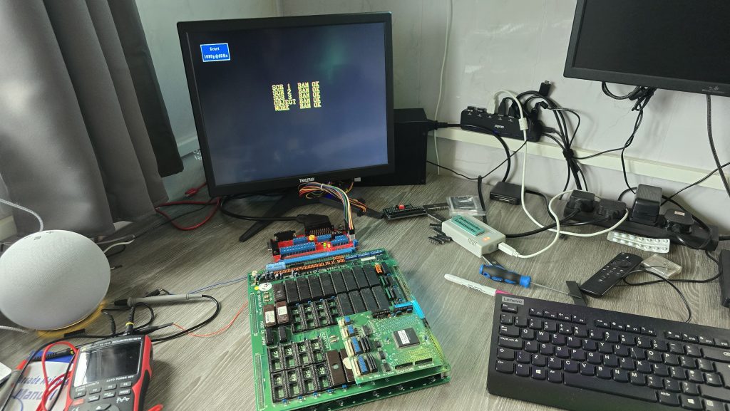
I started by connecting up the two arcade boards (Street Fighter II and Caveman Ninja) to see what we get out of them. The Caveman Ninja board had no output at all, but the Streetfighter II board actually had output to the screen, so I decided to start with this board as I figured it would be the easier repair (Yeah, right!).
Upon powering up the board, the game ran through the RAM tests, which all passed. But then it just hung on that screen.
I figured I’d start off with giving the board a good clean up, removing all of the socketed chips, sanding down the pins and giving them all a dose of de-oxit.
The only change in behavior was that the board no longer worked. At this point, I realised my rookie mistake where I had put one of the PAL chips the wrong way around. The writing printed on the chip was upsidedown compared to the others, and I just didn’t check the notch. Very disappointing, but luckily not unrecoverable.
The code for all of the PALs has been reverse-engineered for this board (https://wiki.pldarchive.co.uk/index.php?title=Street_Fighter_2_Champion_Edition), so after I had ordered some GAL16V8s, I programmed one of them with the code and was finally back to square one.
So where do we go from here? Ideally, I need to know what the board is actually trying to do at the point it is crashing. It was at this point that I had an idea. Everybody has surely heard of MAME (Multi Arcade Machine Emulator), which allows you to run Arcade ROMs on many different platforms. However, it also has some advanced features that most people would not have used before, one of which is an internal debugger, which allows you to disassemble the ROM code and also step through the code one instruction at a time, whilst also setting breakpoints and monitoring for specific conditions.
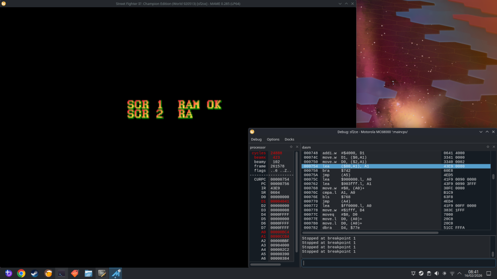
Running the ROM file in MAME, I could see that after the RAM tests, the screen goes blank and then changes the text to Street Fighter II. My board doesn’t get this far, so I needed to concentrate on the code that runs after the last RAM check, but before the screen blanks.
After a bit of playing around, I found a nice breakpoint to set at address 754. This is a loop in the code that prints a character to the screen. So with a breakpoint set here, every time I start the emulator running, it will print one more character to the screen and then pause. This will allow me to step through until the last OK message is written to the screen and then see what happens next.
I could see that during the RAM tests, all it was doing was writing a character into RAM and then reading it back and comparing it. I don’t think this is the most conclusive RAM test, but I guess it’s good enough to find basic RAM issues. I did do a quick check here and manually modified the area of memory so the compare would fail. It responded by marking that RAM test as “NG” (Not Good), and then froze the game. I didn’t need to do this bit as all the tests were passing, but I thought it was interesting.
The next thing I wanted to do was to try to find out where my board was stopping. I had a thought that if I could insert a reboot command into the actual ROM code at various points, I could then burn this to an EPROM and stick it in my board. If my board went into a reboot loop, then I would know that it was getting as far as executing that command.
68000 Assembly is not a speciality of mine, so I used AI to help here (sometimes it does actually have some uses!). My first attempts used a jump instruction to jump to address 0 and reset the board, but this had one small issue in that the opcode was 3 words long (6 bytes). The issue with this is that I could only insert it where another 6-byte opcode existed; otherwise, I would be overwriting other code. Asking AI for another way of rebooting the board, it suggested the opcode “ILLEGAL” which has a hex code of 4AFC. With this being 1 word long, I could insert it anywhere in the ROM without breaking anything.
I gave it a quick test and confirmed that my board did indeed reboot when it hit this command. I continued going through the code in chunks and added my reboot at various points to see how far my code was executing.
I eventually homed in on the exact part of the code where the board was stopping.
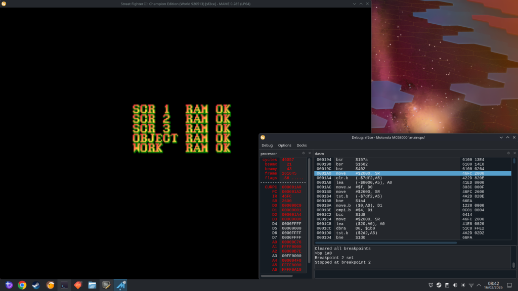
The culprit was an opcode stored at the address 1A0:
MOVE $2000, SR
Giving AI another chance to show its uses. I asked what this command did. It turns out this command essentially changes the Status Registers on the CPU. With the value of $2000, it would achieve the following:
Out of those options, I already had a hunch of which one to concentrate on. Going back to the MAME debugger, after the command at 1A0, the next instruction executed was at address 5C6. But there was no jump instruction, so why did it suddenly jump to that address? One logical answer is that an interrupt was triggered.
A bit more research showed that on the 68K CPU, when an interrupt is triggered, it will jump to the address held in the interrupt vector relating to that interrupt. These values are located in the address range 60 to $7C, and looking at that area in the ROM file, I could see 05C6 listed, which confirmed to me that an interrupt was indeed being triggered that was causing the code to jump to address 5C6. The problem now is that my board never triggers that interrupt.
The 68k CPU has 3 interrupt pins, which are inputs. Each one of these can either be high or low, giving us 3 binary bits, and a total of 8 possible combinations.
According to the schematics for the CPS1 board, one of these interrupts is tied to 5V, which I confirmed with my scope. That left two other interrupt pins. I monitored both of these on my scope, and both of them remained permanently high.
The interrupt signal is an active low signal, so with all these staying high, no interrupt would ever be triggered, and my board would just sit there waiting for this signal. I traced the Interrupt pins on my board back to a 74LS74, which is a dual positive-edge-triggered flip-flop. I took a look at the datasheet for this IC and probed the input pins. One of the pins had a regular pulse to it, and looking at the schematics, this signal was the vertical blank signal.
With this input being triggered, the output pin going to the CPU should also be triggered. So it looks like the first issue to be identified is actually a faulty 74LS chip.
One last thing I could try before wrapping up this part of the repair was to replicate the interrupt being triggered. I could do this by simply shorting this signal to ground. Since the vertical blank signal was a continuous pulse. I replicated this by just tapping a ground wire onto the interrupt pin. With this, I was able to “run” the game frame by frame.
There is another issue in that the background graphics are corrupted. But that will be a problem for another day, after I have got the board at least running the code.
Stay tuned for part 2 once the new 74LS74 chips have arrived
Recently, a colleague at work contacted me and asked if I wanted some old computer stuff, including a 19″ CRT monitor and a colour Dot Matrix printer. This donation was gladly accepted, and whilst collecting my new toys, we found ourselves discussing various retro tech.
During this conversation, he mentioned that he had a Yamaha DX7 synthesiser that he had purchased, but it had a fault. It is very common for the batteries to die on these, which then leads to corrupted content in the RAM. In this case, though, the battery had already been replaced, but it didn’t fix the issue.
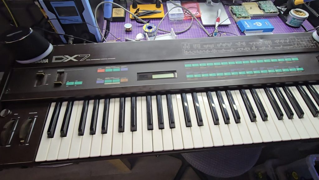
I did a quick Google search for the schematics, and essentially what I saw were the schematics of an 8-bit microcomputer. I said I’d take it back with me and take a look to see what was going wrong. Occasionally, the keyboard would appear to boot up, but would then hang, other times, the display would be garbled and completely unresponsive.
I knew the CPU was trying to run code because the display was occasionally showing correct text. Just to rule out a ROM chip issue, I downloaded the ROM file from the internet and compared it with the ROM stored on this chip. All looked ok, but I wrote the ROM to a new chip anyway and tested with the same result.
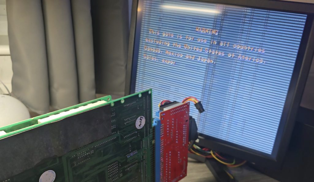
I then grabbed my scope and started probing the pins on the ROM chip to see what the address bus and data buses looked like. It was with the scope that I saw the issue, or at least the first issue. The data bus pins were all looking good with nice strong 5V peak-to-peak signals. But the first 8 address bus pins (0 to 7) were all a lot lower. Address bus pins 8-15 were all working as expected.
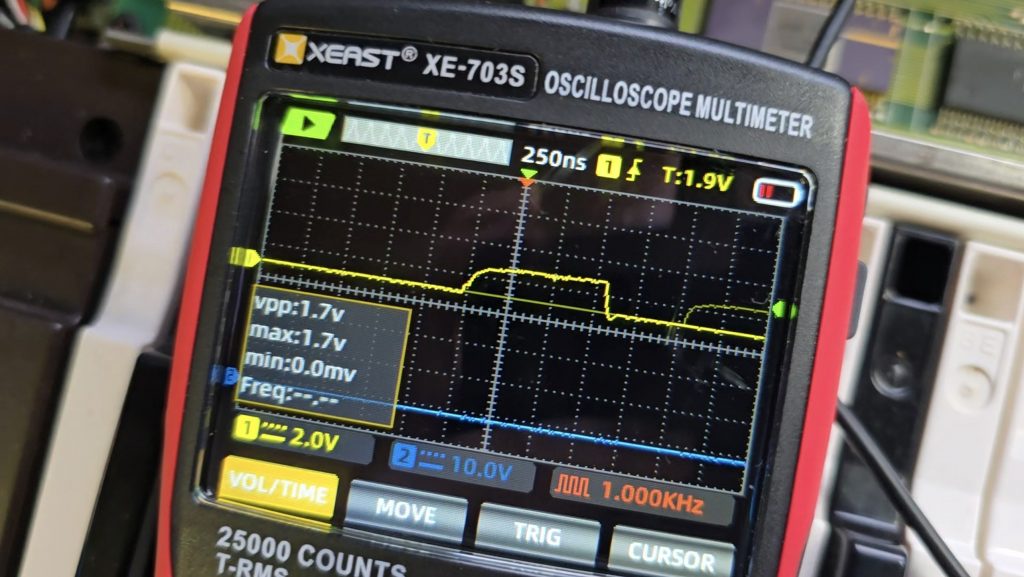
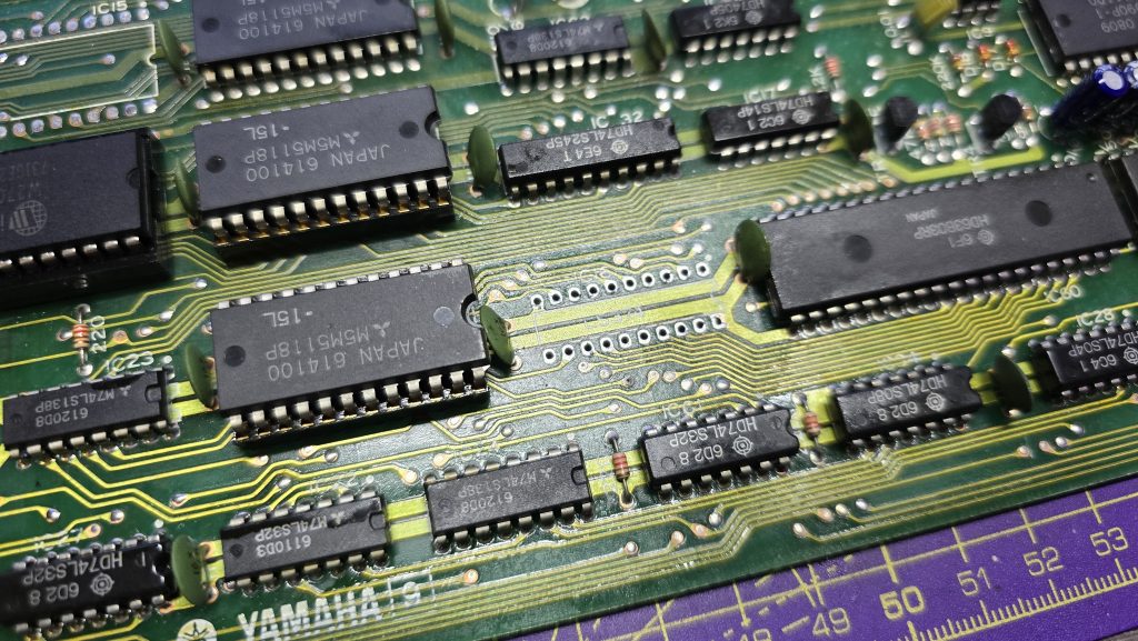
I dragged out the schematics and did a quick glance around for something that was only connected to the first 8 address bus pins. There was one very obvious candidate, a 74LS374 transparent latch IC that sat between the address bus and the ROM chip. Looking at the inputs of this IC showed they were nice and strong with no issues, but all the outputs were low, as shown in the picture above.
I suspected that this chip was faulty, but it could still be another IC on the board pulling the outputs low. So to test for that, I snipped one of the output pins so it was floating, then measured again. Exactly the same issue. At this point, I then removed the IC from the board, ready for the replacement chip to arrive.
Now off the board, I tested the chip in my chip tester just out of curiosity. It did indeed state that the device was faulty. I will be testing the new ones when they arrive, as I’ve not used this chip tester before, so not sure how much trust to put into it yet.
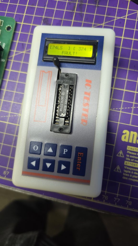
All I need to do now is await the delivery of the new IC and hopefully, this classic synth will be back up and running again. I will of course update everyone with the result, and hopefully this is the only fault 🙂
I decided I wanted to pick up an Epson HX20. The fact that it has a built-in dot matrix printer seemed like it would be a pretty cool thing to mess around with.
After a bit of research, I discovered the main issue is that they came with a Ni-Cad battery installed, which usually leaks and causes damage to the computer. But a bad trace or two should be a simple enough fix, right?
So I trawled eBay and found a spares and repair unit for a cheap price. After all, I didn’t want to spend much on a computer that has a high chance of not working. And the majority of these computers are sold as untested or spares and repairs for that very reason.
Well, the device turned up, and upon unpacking it, I could already smell the leaking battery, but this was expected, so I took it apart to check out the LCD board, which normally takes most of the damage. I gave it a quick inspection to see if any damage was visible. And, well, yes, there was some visible damage lol.

From what I could see, a large number of traces were destroyed. So let this be a warning to anyone who is going to take a chance on one of these, if it’s “untested”, this is probably the state of it!
I downloaded the schematics and started testing the connections and marking off which ones were not connected. After a while of doing this, it became apparent that this board was pretty much destroyed. But I didn’t instantly give up (Although I probably should have).
I wanted to try one other thing: could I actually remake the board from scratch? This was a very ambitious project, and I didn’t really hold out much hope, but I think on the first attempt, I actually got a lot further than I expected.
I spent quite some time designing the PCB and re-creating some of the components in Easy EDA, as they weren’t in any of the libraries. The LCD screen for example, needed to be measured precisely and drawn manually.
Eventually, I ended up with this:


I had to manually route quite a lot of the connections, as the auto routers just couldn’t work it out, even on a 4-layer PCB.
But eventually, I ended up with a PCB that said all traces were connected. So I took the plunge and placed an order with JLCPCB. When they arrived, I then had the next challenge of unsoldering all the original parts and re-fitting them to my new PCB.
It was then time to give it a test. Would I see anything? Would lots of smoke pour from the display?
Well, to my surprise, it actually kind of worked. The main issue I had though, was that the alignment and fitment of the LCD screen wasn’t perfect, and I think the pin spacing was also very slightly out.

So, to be fair, I think I did a pretty good job and probably went above and beyond what anyone else would do to try and recover one of these computers.
I have proved that the actual computer itself is working fine, but I didn’t test the printer or tape drive on this unit. Now I have one of the boards made up, which I can directly compare against the original board, I can see some errors that if corrected, may actually get this working again 100%.
The problem is, changing these parts means a complete re-route of all the PCB traces again, which was quite time-consuming the first time around.
For now, I took the coward’s way out and purchased another HX20, which is nearly fully working and the only issue is with the cassette drive, which I think I can handle! I also tested the expansion unit from the old machine and tested it with the new one, so confirmed that it works fine.
So here is the new machine in all it’s glory!

I think I may give the LCD board another go, as it would probably be useful to the community to recover from this common fault on the HX20s. But, I also think I may take a break for a little while first, as my dreams have been haunted by routing PCB traces
When I recieved this MSX2, I had concerns as it had certainly already had a reapair attempted on it. What if this person had tried everything and discovered that a custom chip had blown and it was unrepairable?
Well, I decided to carry on regardless and work through the issue myself. To start off with I checked the basics on the CPU. Clock signal, reset circuit, data and address buses. They all looked fine.
The video circuit all seemed to be operational, I could see the 15khz sync signal but the composite video output was just black.
I noticed that the CAS signal for the main RAM was missing, which suggested that the CPU wasn’t successfully executing code, even though there was a bunch of activity going on. My first assumption was bad memory. I socketed both the video RAM and the main RAM and swapped chips around but it made no difference.
I decided to add a useful tool to my inventory and purchased a mini DRAM tester off Ebay.

One by one I inserted the DRAM chips and they all tested good. Not quite as simple as a RAM fault then.
After reading through the schematics for the Sony HB-F1XD (The closest MSX2 I could find to my model) I noticed the VDP read and write signals came from a custom IC on the board labelled as a MB64H444.
I checked with my thermal camera and noticed this chip stayed completely cold when powered on. My first concern was maybe this chip was completely dead which would be game over for this computer as they are virtually impossible to purchase.
I found the pinout for this chip and probed every pin with my scope. Everything seemed to be in order.
It was at this point that I put the scope back on the composite video pin and noticed it was showing a signal!
How could this be? I’ve not changed anything!
Even though I don’t have the replacement hic board yet, I hard wired the composite video output from the vdp chip into my little monitor and there it was, a perfect working image.

Although I was happy that the computer was working and that all of the custom chips were good. I don’t like things just fixing themselves as it can always break again.
And that is exactly what happened. But I discovered that by putting some pressure on the board I could break and fix the computer at will.
My next job was to find the bad connection, so I started re-flowing the solder joints on the chips in the area where I was bending the board. I also reflowed the solder on the MB64H444 chip. At this point the computer was non working and bending the board wouldn’t bring it back to life. Back to square one 😞
Only this time, I knew all the components were working and I was looking for a bad trace or solder joint.
I went back over the MB64H444 IC as this was the last thing I touched, and that is when I noticed no activity on the A13 address line. Could it really be that simple?
As a temporary test, I soldered a bodge wire from A13 on the MB64H444 up to A13 on the ROM chip.

I crossed my fingers and powered on the machine which greeted me immediately with the MSX logo. And no amount of flexing the board would cause it to not work.
The entire computer brought to a halt because of a bad trace on one of the address lines to this MB64H444 chip.
I’m still not 100% sure what role this chip plays in this computer. The schematics list it as a speed controller. So I will be doing some more reading up now to see why this issue caused the machine to not boot.
I have alsp sourced a modern replacement for the HIC board now, so once this arrives, I will be able to put this computer fully back together and start using it.
There is something so satisfying when you finally find the issue with these old machines.
If you have anything sat in your loft broken and you fancy donating it, I will do my best to bring any computer back from the dead and give it a good home 😀
My next repair project is this Sony MSX2 computer. Purchased as not working (black screen).

Unfortunately this machine has a bit more to its history than the eBay advert let on. Upon opening it I noticed that the problematic HIC1 board (The video out multiplexer that tends to suffer from corrosion on these machines) was not only missing, but pin headers had been fitted in its place.
This tells me two things. The hic board on this machine had indeed failed. But also, someone had replaced it with the modern replacement hic board but I guess it still didn’t fix the problem so they took it back out and sold the computer.

So, I need to either build or source a hic board for starters. But even then I probably still need to get the actual machine running.
I have already gone over the board with my scope to see if I can see what is going on. For starters it seems the computer tries to start for a few seconds and then comes to a stop. I can see a horizontal sync and csync but it appears the video signal is just a black screen.
I’ve also noticed that the CAS signal for the system memory is not there. Currently I’m assuming a possible memory fault so I will try swapping that out first. If it still doesn’t appear to be running then I will probably look into the ROM chip next.
All of this is under the assumption that the MSX2 should actually run fine even without the hic board present. Unfortunately I don’t have another MSX2 to test this theory.
This is going to be fun 😁
When I first started building my mini pinball cabinet, it was designed to be powered by the Steamdeck. This was mainly because I didn’t have a spare PC kicking around that could do the job.
The Steamdeck has being doing the job, but it had one issue, the loading times! Because the pinball software runs on Windows, I was booting Windows on the Steamdeck from Micro SD. Yes, I could have installed Windows on the Internal storage, but I didn’t want to mess around with dual booting and I wanted to actually use the steam deck for its intended purpose with Steam OS.
I decided I needed a dedicated machine to run the cab moving forwards, but I didn’t want something that was going to take up a load of space. So after looking around at various Mini PCs I decided to give the AceMagician AMR5 a go. This little PC runs an AMD 5800U processor with integrated GPU which I figured should do the job for my little 1080p cabinet. It also has a 512gb SSD and 16gb of RAM.

The PC has a USB-C port on the front so the cable that used to plug into the Steamdeck now just plugs into this. After running the Baller Installer and doing a few extra tweaks, my cabinet was back up and running, but now with amazing boot/load times.
All I need to do now is finish off the physical appearance of the cabinet and then setup some additional tables to play on.


A while ago I purchased some UV overlays for the Vectrex. These overlays require a UV light source to make them glow. At the time when I purchased them, my 3D printer couldn’t handle the size of the Vectrex screen so I made a frame using multiple 3D printed parts and glued them together.
I was never really happy with the design though so decided now I have larger printers, I would re-visit this project.
I also decided to experiment which switching filament during the print so I could use transparent filament as a diffuser.
This still may not be my final version, but I am pretty happy with how this has turned out for nowadays


After another busy couple of weeks, I finally have my new retro room/workshop in a possition where I can start to enjoy it.
Obviously, a room like this is never truly finished, but at least I can now escape from the real world and have a nice place to relax.
So let’s have a quick tour!
We start off with my workbench area. This is where I will spend my time fixing old computers/consoles and tinkering with developing hardware for old systems. I also have a PC in the corner which I use for creating models for 3D printing.

Next, we move around to the 3D Printer zone. I have a resin printer on the workbench above, but mostly I use the FDM printers. The K1 MAX is my go-to printer, but recently I also purchased a Neptune Max 4 which has a huge build volume. I’m looking to use that for printing a replacement computer case in the near future. I also have a vinyl sign cutter which is very useful for creating logos etc.

Next, we move on to the console area. Everything is now connected up using Wi-Fi smart switches and automatic Scart switches so everything is playable within seconds.


We now go around to my modern gaming PC which I mainly use for VR gaming with the Meta Quest 3. I also have my bookshelf filled with games from various systems.

Next in line is the retro computer setup. I have some of my favourite computers set up here, but can swap them out with other systems when required. The black monitors are 4:3 HDMI monitors off amazon and a couple of them have OSSC Scart converters connected so I can connect any system up via RGB Scart.

And finally, my home-made mini arcade cabinet and my work-in-progress virtual pinball machine.
I will see about doing a video shortly of everything up and running. You get that real arcade vibe once you have multiple systems all blasting out their own game music.